2 division of the ssi data word into partwords, 6encoder evaluation – Lenze 9400 User Manual
Page 254
6
Encoder evaluation
6.3
Parameter setting
254
Lenze · Servo-Inverter 9400 HighLine · Reference manual · DMS 10.0 EN · 11/2013 · TD05/06
_ _ _ _ _ _ _ _ _ _ _ _ _ _ _ _ _ _ _ _ _ _ _ _ _ _ _ _ _ _ _ _ _ _ _ _ _ _ _ _ _ _ _ _ _ _ _ _ _ _ _ _ _ _ _ _ _ _ _ _ _ _ _ _
6.3.8.2
Division of the SSI data word into partwords
The
SB can be configured so that it splits up the SSI data word received by the
encoder interface into several partwords.
• A separation into partwords is reasonable if the SSI data word also contains other data (like for
instance fault or status information) in addition to the position.
• The max. 8 possible partwords are fixedly assigned to the outputs SSI_dwDataword_1 ...
SSI_dwDataword_8.
• The partwords are configured via the following parameters:
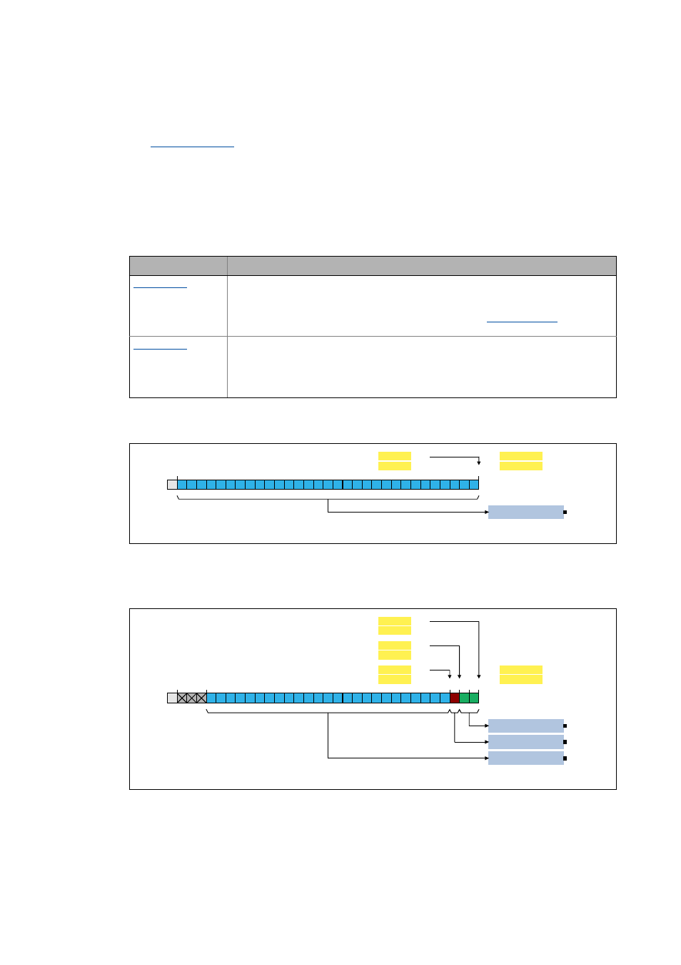
• In the Lenze setting the complete SSI data word received is shown at the output
SSI_dwDataword_1:
[6-7]
Example 1: Lenze setting
• The following example shows the parameterisation required to split up the SSI data word
received into three partwords (here status information, error bit, and position information):
[6-8]
Example 2: Splitting up the SSI data word received into three partwords
Parameter
Info
Starting position for partwords 1 ... 8
In order to be able to display the individual components of the SSI data word received at
different outputs, this code serves to specify the bit position with which the partword for the
respective output starts for the eight possible outputs of the
Subcode 1 is fixedly assigned to the first output, subcode 2 to the second output, etc.
Length of the partwords 1 ... 8
Apart from the position of the first bit, also the bit length of each partword is important for
the separation. A length of zero means that no partword is to be shown at the corresponding
output (output = 0). Here also subcode 1 is fixedly assigned to the first output, subcode 2 to
the second output, etc.
S = start bit
position information
&
&
66,BGZ'DWDZRUGB
3DUWZRUG/HQJWK
3DUWZRUG6WDUWSRVLWLRQ
n
&
&
6
S = start bit
Status information
Error bit
Position information
&
&
66,BGZ'DWDZRUGB
&
&
&
&
66,BGZ'DWDZRUGB
66,BGZ'DWDZRUGB
3DUWZRUG/HQJWK
3DUWZRUG6WDUWSRVLWLRQ
3DUWZRUG/HQJWK
3DUWZRUG6WDUWSRVLWLRQ
3DUWZRUG/HQJWK
3DUWZRUG6WDUWSRVLWLRQ
o
p
n
&
&
6