2 signal configuration, Signal configuration ( 523), 11 basic drive functions – Lenze 9400 User Manual
Page 523
Lenze · Servo-Inverter 9400 HighLine · Reference manual · DMS 10.0 EN · 11/2013 · TD05/06
523
11
Basic drive functions
11.12
Brake control
_ _ _ _ _ _ _ _ _ _ _ _ _ _ _ _ _ _ _ _ _ _ _ _ _ _ _ _ _ _ _ _ _ _ _ _ _ _ _ _ _ _ _ _ _ _ _ _ _ _ _ _ _ _ _ _ _ _ _ _ _ _ _ _
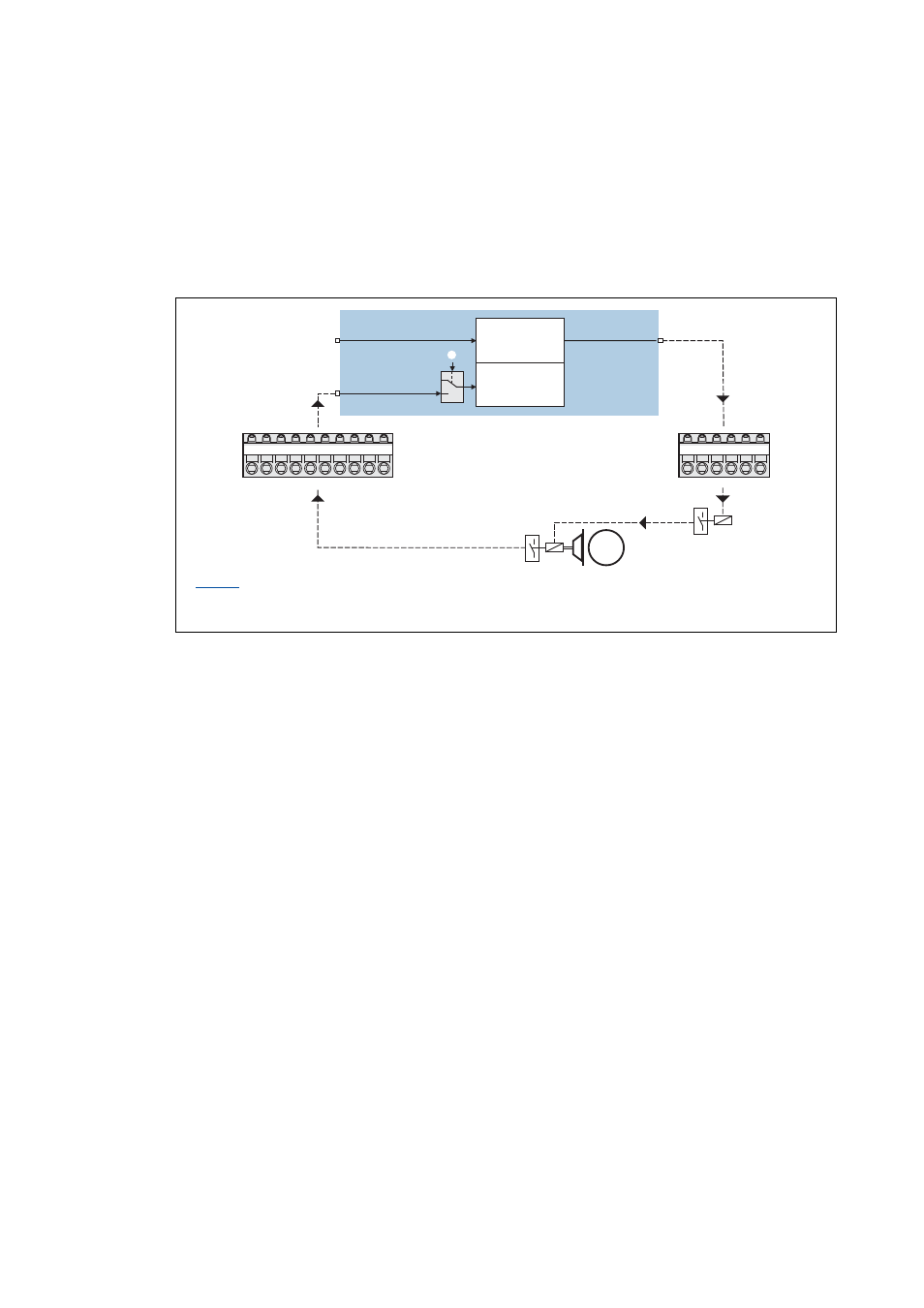
11.12.2.2 Signal configuration
The signal configuration of the control and status signals for the brake logic and monitoring
function is executed via the parameters shown in the following signal flows.
Direct brake control
This triggering of the holding brake does not need the motor brake control module:
[11-29] Direct control of the motor holding brake
: Status input monitoring
Brake control via relay/contactor at digital output
Feedback by "Brake function test"
1
0
M
GI
RFR
DI1
DI2
DI3
DI4
DI5
DI6
DI7
DI8
GO
24O
DO1
DO2
DO3
DO4
?
bBrakeApplied
bReleaseBrake
bReleaseBrakeOut
1
0
Digital I/O
Digital I/O
Brake logic
Monitoring