3 "ls_digitaloutput" system block, Ls_digitaloutput" system block, 8i/o terminals – Lenze 9400 User Manual
Page 282
8
I/O terminals
8.5
Digital outputs
282
Lenze · Servo-Inverter 9400 HighLine · Reference manual · DMS 10.0 EN · 11/2013 · TD05/06
_ _ _ _ _ _ _ _ _ _ _ _ _ _ _ _ _ _ _ _ _ _ _ _ _ _ _ _ _ _ _ _ _ _ _ _ _ _ _ _ _ _ _ _ _ _ _ _ _ _ _ _ _ _ _ _ _ _ _ _ _ _ _ _
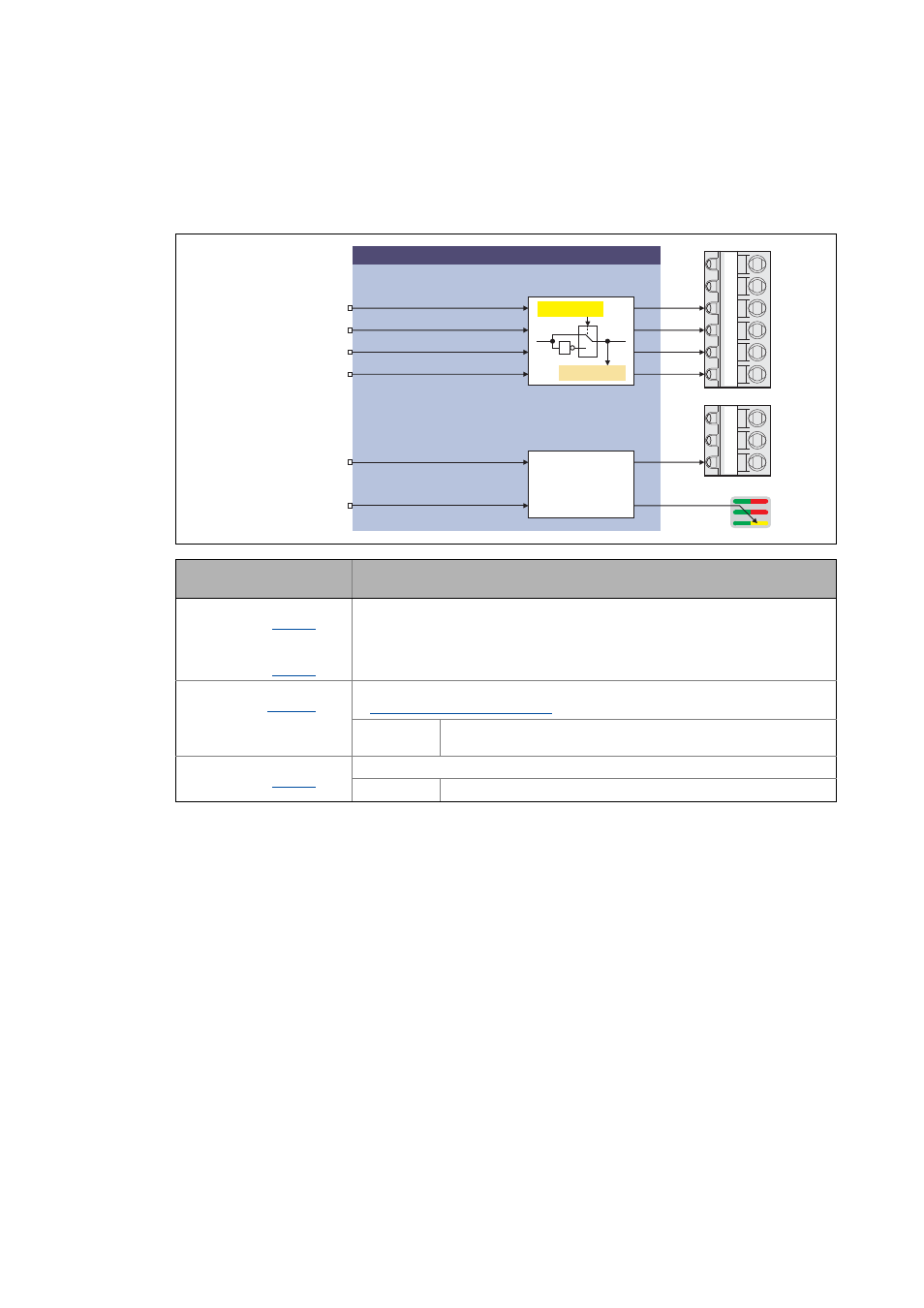
8.5.3
"LS_DigitalOutput" system block
In the function block editor the LS_DigitalOutput system block provides the interface to the digital
outputs, the state bus, and the yellow user LED at the front of the controller.
Input
DIS code | data type
Information/possible settings
DIGOUT_bOut1
| BOOL
...
DIGOUT_bOut4
| BOOL
Digital output 1 ... 4
DIGOUT_bStateBusOut
| BOOL
Setting the state bus to the "Error" state
"State bus" monitoring function ( 283)
TRUE The state bus is set to LOW level, all nodes connected to the state bus
start their pre-programmed response.
DIGOUT_bUserLED
| BOOL
Control of yellow user LED on the front of the controller
TRUE LED on
GO
24O
DO1
DO2
DO3
DO4
LS_DigitalOutput
DIGOUT_bOut1
DIGOUT_bStateBusOut
DIGOUT_bOut3
DIGOUT_bOut2
X4
1
0
1
C00118/1...4
DIGOUT_bOut4
DIGOUT_bUserLED
User LED
C00444/1...4
GE
24E
SB
X2
CONTROL