Can on board: bus off [0x00830000, Can on board: invalid node address 0 [0x00830001, 0x00830002 – Lenze 9400 User Manual
Page 665: 0x00830000, 0x00830001, 0x007f0004, 13 diagnostics & fault analysis
Lenze · Servo-Inverter 9400 HighLine · Reference manual · DMS 10.0 EN · 11/2013 · TD05/06
665
13
Diagnostics & fault analysis
13.7
Error messages of the operating system
_ _ _ _ _ _ _ _ _ _ _ _ _ _ _ _ _ _ _ _ _ _ _ _ _ _ _ _ _ _ _ _ _ _ _ _ _ _ _ _ _ _ _ _ _ _ _ _ _ _ _ _ _ _ _ _ _ _ _ _ _ _ _ _
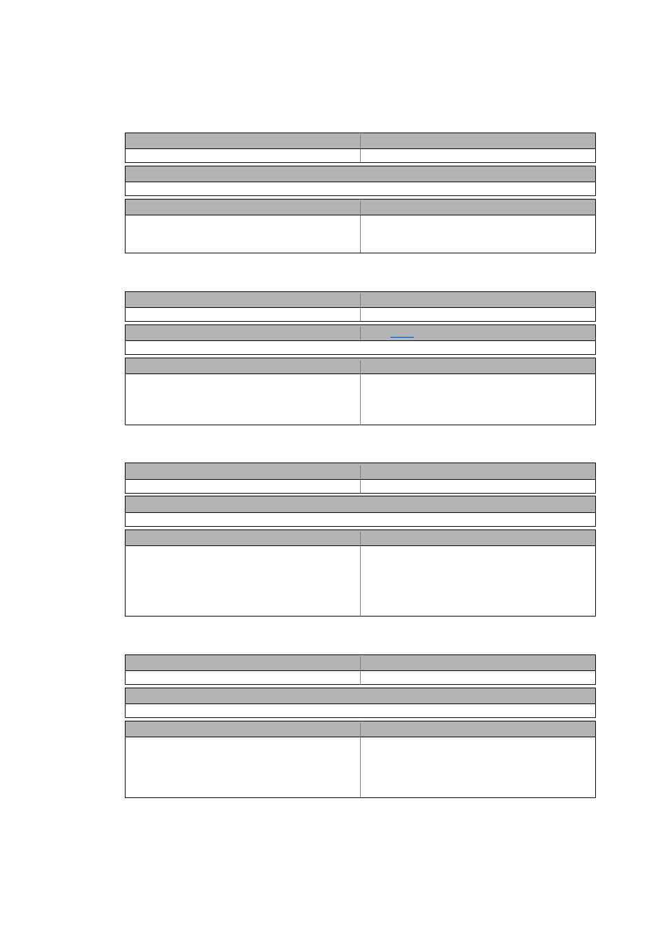
Communication with module in MXI2 interrupted [0x007f0004]
CAN on board: Bus off [0x00830000]
CAN on board: Invalid node address 0 [0x00830001]
CAN on board: Basic configuration invalid [0x00830002]
Module ID (decimal)
Error ID (decimal)
127: Interface to the intelligent communication module
4
Response (Lenze setting printed in bold)
None System fault Fault Trouble Quick stop by trouble Warning locked Warning Information
Cause
Remedy
Communication between the controller and the
extension module in module slot MXI2 cannot be
established.
• Switch off controller, plug module correctly in module
slot MXI2, switch on controller again.
• If the problem occurs again, replace the module.
Module ID (decimal)
Error ID (decimal)
131: "CAN on board": CAN dispatcher
0
Response (Lenze setting printed in bold)
Setting:
( Adjustable response)
None System fault Fault Trouble Quick stop by trouble Warning locked Warning Information
Cause
Remedy
CAN on board: "Bus-Off" state
• Received too many faulty telegrams.
• Defective cable (e.g. loose contact).
• Two nodes with the same ID.
• Remove fault (e.g. EMC).
• Remove loose contact, screw down adapter.
• Assign different IDs to nodes.
Module ID (decimal)
Error ID (decimal)
131: "CAN on board": CAN dispatcher
1
Response (Lenze setting printed in bold)
None System fault Fault Trouble Quick stop by trouble Warning locked Warning Information
Cause
Remedy
CAN on board: initialisation error
• The hardware allocation of the node address was
selected via DIP switches, and the DIP switches of the
node address are all on zero.
Note: Instead of the impermissible node address 0, node
address 1 is used.
• Set a non-zero node address by means of the DIP
switches and then switch mains.
• Activation of the software allocation of the node
number by switching over DIP switch 2, then switch
mains.
Module ID (decimal)
Error ID (decimal)
131: "CAN on board": CAN dispatcher
2
Response (Lenze setting printed in bold)
None System fault Fault Trouble Quick stop by trouble Warning locked Warning Information
Cause
Remedy
CAN on board: configuration error
• Faulty download of an Engineer or PLC Designer
project
• Invalid CAN settings according to DS301V402 in the
Engineer or PLC Designer.
• Repeat download
• Correct CAN settings in the project and regenerate
project.