2 parameter setting, 3 reconfiguring analog input 1 into current input, Parameter setting – Lenze 9400 User Manual
Page 275: Reconfiguring analog input 1 into current input, 8i/o terminals
Lenze · Servo-Inverter 9400 HighLine · Reference manual · DMS 10.0 EN · 11/2013 · TD05/06
275
8
I/O terminals
8.2
Analog inputs
_ _ _ _ _ _ _ _ _ _ _ _ _ _ _ _ _ _ _ _ _ _ _ _ _ _ _ _ _ _ _ _ _ _ _ _ _ _ _ _ _ _ _ _ _ _ _ _ _ _ _ _ _ _ _ _ _ _ _ _ _ _ _ _
8.2.2
Parameter setting
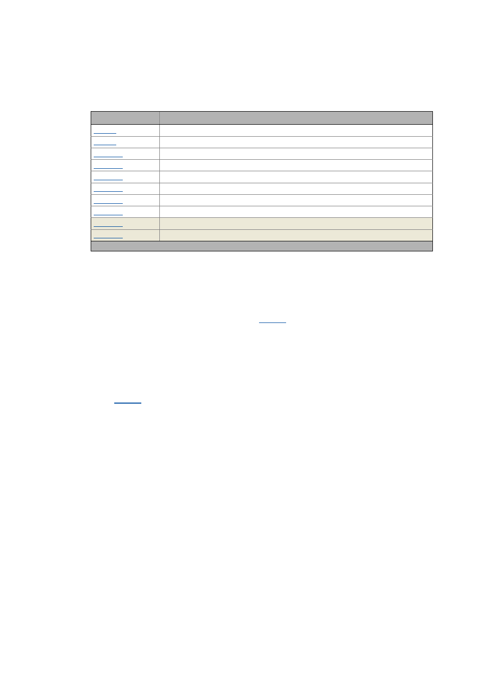
Short overview of parameters for the analog inputs:
8.2.3
Reconfiguring analog input 1 into current input
By means of the following two steps, analog input 1 can be reconfigured into a current input:
1. Bridge the terminals A1R and A1- at terminal strip X3 by means of wiring.
2. Select the corresponding current loop under
Tip!
Like this you can implement a 4 ...20 mA current loop, e.g. for speed setpoint selection.
Open-circuit monitoring
Under
you can set an error response to open circuit for the 4 ...20 mA current loop.
Parameter
Info
Config. analog input 1
Resp. to open circuit AIN1
Analog input 1: Gain
Analog input 2: Gain
Analog input 1: Offset
Analog input 2: Offset
Analog input 1: Dead band
Analog input 2: Dead band
Analog input 1: Input signal (-16384 ≡ -100 %, 16383 ≡ 100 %)
Analog input 2: Input signal (-16384 ≡ -100 %, 16383 ≡ 100 %)
Greyed out = display parameter