1 signal flow, Signal flow, 5motor interface – Lenze 9400 User Manual
Page 198: 7 v/f control (vfcplus) 198
5
Motor interface
5.7
V/f control (VFCplus)
198
Lenze · Servo-Inverter 9400 HighLine · Reference manual · DMS 10.0 EN · 11/2013 · TD05/06
_ _ _ _ _ _ _ _ _ _ _ _ _ _ _ _ _ _ _ _ _ _ _ _ _ _ _ _ _ _ _ _ _ _ _ _ _ _ _ _ _ _ _ _ _ _ _ _ _ _ _ _ _ _ _ _ _ _ _ _ _ _ _ _
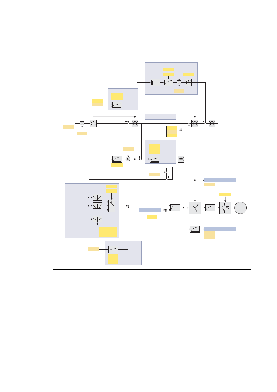
5.7.1
Signal flow
[5-21] Signal flow for closed loop V/f control
C00052
C00963
C00783
C00018
M
C00964
MI_dnActualMotorVoltage_n
MCTRL_dwMotorVoltageAct
(1)
C00059
C00050
C00780
C00022
C00972
C00973
C00011
C00059
C00971
(9)
C00050
C00967
C00968
C00967
C00958
C00959
C00054
C00957
a +b
2
2
C00950
MI_dnBoostSet_n
fmax
fmax
fmax
(3)
C00059
C00497
C00051
MCTRL_dnMotorFreqAct
MI_dnActualMotorFreq_s
C00784
(2)
(4)
(6)
(7)
(8)
1
0
2
C00953/1...11
C00954/1...11
C00952/1...11
C00960
C00971
fmax = f(C00018, C00059)
C00951
Gain
Gain
Reset time
Actual Q-current
Number of pole pairs
Imax controller
Speed setpoint
Actual motor current
Maximum current
Gain
Reset time
Speed controller
Motor reference speed
Motor pole pair number
Feedback influence
Time constant
Limitation
Speed setpoint
Oscillation damping
Gain
Reset time
VVC controller
Motor current
Current setpoint
Characteristic
calculation
Number of pole pairs
Actual speed value
Unfiltered actual speed value
Filter time constant
Motor voltage
Switching frequency
Coordinate
transformation
Inverter error
characteristic
fmax
Frequency values 1...11
Voltage values 1...11
Activat. of interpolat. point 1...11
Linear
characteristic
Square-law
characteristic
User-definable
characteristic
Charact. shape
Base frequency
Influence
V/f voltage boost