5motor interface – Lenze 9400 User Manual
Page 202
5
Motor interface
5.8
Parameterisable additional functions
202
Lenze · Servo-Inverter 9400 HighLine · Reference manual · DMS 10.0 EN · 11/2013 · TD05/06
_ _ _ _ _ _ _ _ _ _ _ _ _ _ _ _ _ _ _ _ _ _ _ _ _ _ _ _ _ _ _ _ _ _ _ _ _ _ _ _ _ _ _ _ _ _ _ _ _ _ _ _ _ _ _ _ _ _ _ _ _ _ _ _
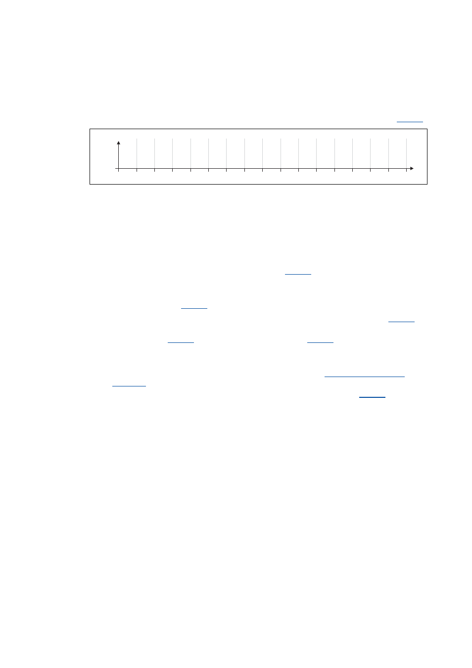
Distribution of the interpolation points
• The saturation characteristic is defined by 17 interpolation points which are distributed linearly
on the x axis.
• Interpolation point 17 represents 100 % of the maximum motor current in the process (
[5-23] Saturation characteristic: Distribution of the interpolation points
Example for determining the saturation characteristic
Given values:
• Rated motor current: 5 A
• Maximum motor current: 20 A
• Maximum process current: 15 A (must be set later in
)
Procedure:
1. Deactivate correction (
= "OFF").
2. Set the maximum current up to which the motor is to be operated in the process in
(in
this example "15 A").
• The value set in
has to be greater or the same as
.
3. Adjust the current controller with different current setpoints and take down the corresponding
settings for Vp and Tn.
• The procedure for the adjustment is described in the chapter "
• The current setpoints that are to be set for the respective adjustment in
result from
the scaling of the maximum process current to the x axis of the saturation characteristic.
• The interpolation points which are required to define the saturation characteristic with a
sufficient quality varies from motor to motor and thus has to be determined individually.
0
6.25
12.5
18.75
25
31.25
37.5
43.75
50
56.25
62.5
68.75
75
81.25
87.5
93.75
100
I
max
Vp
Tn
[V/A]
[ms]
2
3
4
5
6
7
8
9
10
11
12
13
14
15
16
17
[%]
1