5motor interface – Lenze 9400 User Manual
Page 194
5
Motor interface
5.6
V/f control (VFCplus)
194
Lenze · Servo-Inverter 9400 HighLine · Reference manual · DMS 10.0 EN · 11/2013 · TD05/06
_ _ _ _ _ _ _ _ _ _ _ _ _ _ _ _ _ _ _ _ _ _ _ _ _ _ _ _ _ _ _ _ _ _ _ _ _ _ _ _ _ _ _ _ _ _ _ _ _ _ _ _ _ _ _ _ _ _ _ _ _ _ _ _
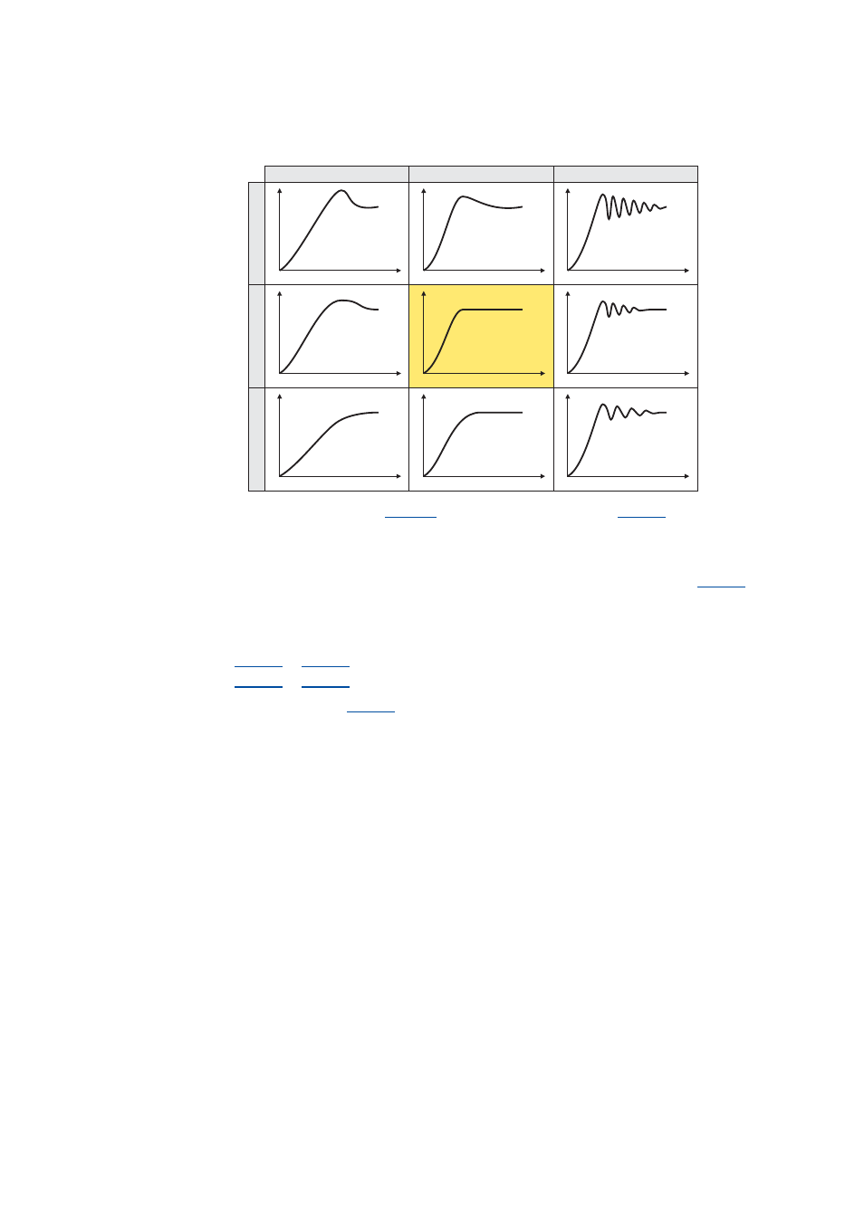
5. Evaluate the step response:
6. Change the gain Vp under
.
7. Repeat steps 4 ... 6 until the optimum step response of the motor current is reached.
• In the optimised state the current rise time typically is 0.5 ... 1 ms.
8. After the optimisation has been completed, deactivate the test mode again (
= "0:
Test mode deactivated").
9. If the Imin control is used, both calculated controller parameters can also be used for the
Imin controller:
•
(Imin controller: gain)
•
(Imin controller: reset time )
10. Save parameter set (
= "11: Save start parameters").
I
t
I
t
I
t
I
t
I
t
I
t
I
t
I
t
I
t
Vp < Vp opt.
Vp = Vp opt.
Vp > Vp opt.
Tn
<
T
n
opt.
Tn
=
T
n
opt.
Tn
>
T
n
opt.