11 resolver error compensation, Resolver error compensation, 6encoder evaluation – Lenze 9400 User Manual
Page 263
Lenze · Servo-Inverter 9400 HighLine · Reference manual · DMS 10.0 EN · 11/2013 · TD05/06
263
6
Encoder evaluation
6.3
Parameter setting
_ _ _ _ _ _ _ _ _ _ _ _ _ _ _ _ _ _ _ _ _ _ _ _ _ _ _ _ _ _ _ _ _ _ _ _ _ _ _ _ _ _ _ _ _ _ _ _ _ _ _ _ _ _ _ _ _ _ _ _ _ _ _ _
6.3.11
Resolver error compensation
This function extension is available from software version V7.0!
Resolver errors typically occur in form of the 1st and 2nd harmonic. They have two different causes:
1. The inductances of the sine and cosine track of the resolver have slightly different values.
2. Sine and cosine track do not magnetise orthogonally to each other.
Resolver errors due to cause 1 can be corrected by adjusting the gains of the digital/analog
converters which feed the resolver tracks. In the Lenze setting, the gains of both resolver tracks are
preset with identical values.
Resolver errors due to cause 2 can be compensated for by a slight correction of the angle via which
both resolver tracks are fed relative to one another.
By executing the device command
= "59: Resolver error identification", the gain of the
digital/analog converter for feeding the resolver and the angle which serves to feed the two resolver
tracks relatively to each other are corrected so that the resolver error is minimised.
• A precondition for the execution of the device command is that the machine is in speed-
controlled operation (servo control). The speed amount during the identification must be
constant and higher than 500 rpm.
• After the resolver error identification has been executed successfully, the resolver error
compensation is activated automatically (
= "1: Activated"). Now the resolver operates
with the following resolver error parameters which have been identified during the procedure:
• The detected gain can take values between 0 ...100 %.
• With a setting of 0 %, the gain of the corresponding resolver track is only 95 % of the default
setting.
• With a sensible resolver error compensation only one of the two gains is adapted. The other
remains at 100 %.
• For a permanent acceptance of the identified resolver error parameters, the parameter set must
be saved (
= "11: Save start parameters").
• When the resolver error compensation is deactivated (
= "0: Deactivated"), the resolver
operates with the Lenze setting again. The identified resolver error parameters remain stored.
The resolver error identification can fail due to the following:
• Wrong control mode is active (no servo control)
• Error or fault is active
• Another identification is active
• The speed is too low (< 500 rpm)
• Time-out while the algorithm is processed
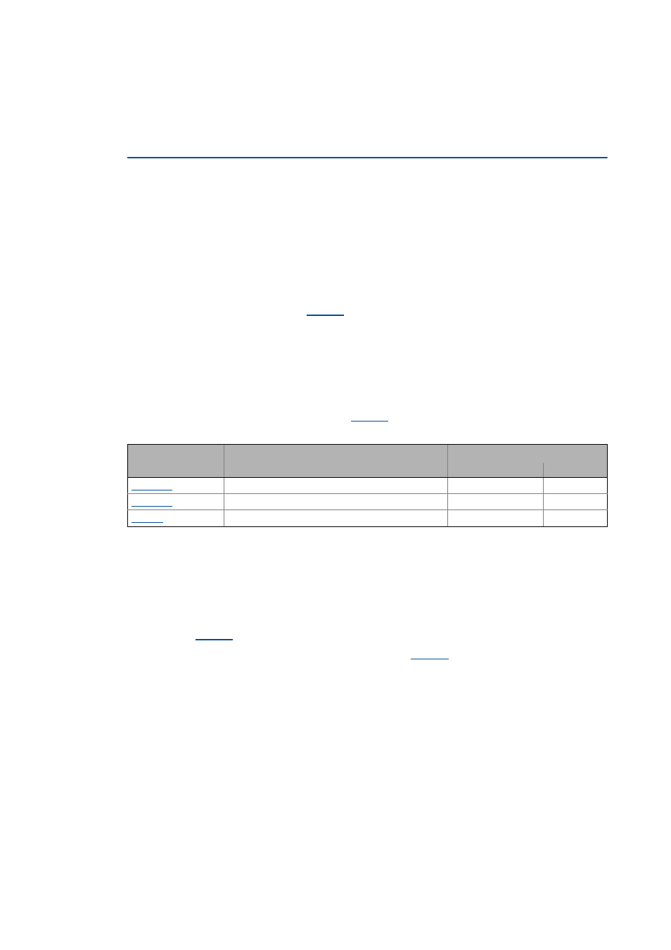
Parameter
Info
Lenze setting
Value Unit
Resolver: cos gain
100 %
Resolver: sine gain
100 %
Resolver: Angle correction
0