2 dead time compensation, Dead time compensation, 8i/o terminals – Lenze 9400 User Manual
Page 287
Lenze · Servo-Inverter 9400 HighLine · Reference manual · DMS 10.0 EN · 11/2013 · TD05/06
287
8
I/O terminals
8.7
Touch probe detection
_ _ _ _ _ _ _ _ _ _ _ _ _ _ _ _ _ _ _ _ _ _ _ _ _ _ _ _ _ _ _ _ _ _ _ _ _ _ _ _ _ _ _ _ _ _ _ _ _ _ _ _ _ _ _ _ _ _ _ _ _ _ _ _
8.7.2
Dead time compensation
For dead time compensation during the detection of the touch probe event, it is possible to select a
delay time (Touch probe delay) in
for each touch probe channel, which will be considered in
the touch probe calculation.
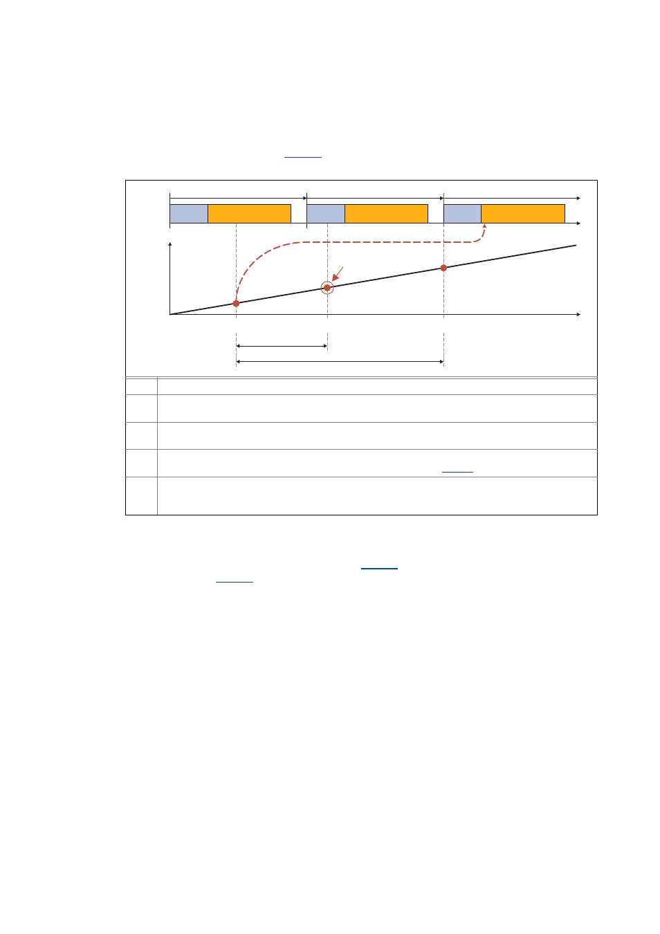
[8-4]
Dead time compensation (principle)
• The filtering of the digital inputs has an impact on the electrical detection of the touch probe,
i. e. the delay time for the digital inputs set in
has to be taken into consideration within
the delay time
• For the optional digital frequency input/output the setting of the delay times is effected via
separate parameters:
• C13021 or C14021: TP delay time - digital frequency input.
• C13061 or C14061: TP delay time - digital frequency output.
Mechanical event: Switch is closed
Electrical event: Closed switch contact is registered
• Can for example be delayed by flying times of the mechanical contact or filter.
Value and position determination for the real (mechanical) event, the determined values are transferred to
the application
Delay time (dead time) between mechanical and electrical event
• This dead time can be compensated by a corresponding setting in
Time considered by touch probe calculation
• If more than one task cycle has elapsed, the two actual position values are searched within a history
buffer, between which the physical event has taken place.
Data
processing
Application
Data
processing
Application
Data
processing
Application
Task cycle
Task cycle
Task cycle
t
Position
t
0
1
2
Delay time
Touch probe received