3 analog outputs, 1 terminal assignment/electrical data, Analog outputs – Lenze 9400 User Manual
Page 277: Terminal assignment/electrical data, Analog outputs ( 277), 8i/o terminals
Lenze · Servo-Inverter 9400 HighLine · Reference manual · DMS 10.0 EN · 11/2013 · TD05/06
277
8
I/O terminals
8.3
Analog outputs
_ _ _ _ _ _ _ _ _ _ _ _ _ _ _ _ _ _ _ _ _ _ _ _ _ _ _ _ _ _ _ _ _ _ _ _ _ _ _ _ _ _ _ _ _ _ _ _ _ _ _ _ _ _ _ _ _ _ _ _ _ _ _ _
8.3
Analog outputs
The controller has two analog outputs that can be used to output internal analog signals as voltage
signals, e.g. for the control of analog indicating instruments or as a setpoint for slave drives.
8.3.1
Terminal assignment/electrical data
Note!
Initialisation behaviour:
• After mains switching until the application is started, the analog outputs remain on
0 V.
Exception handling:
• In the case of a critical exception within the application (e. g. reset), the analog
outputs are set to 0 V.
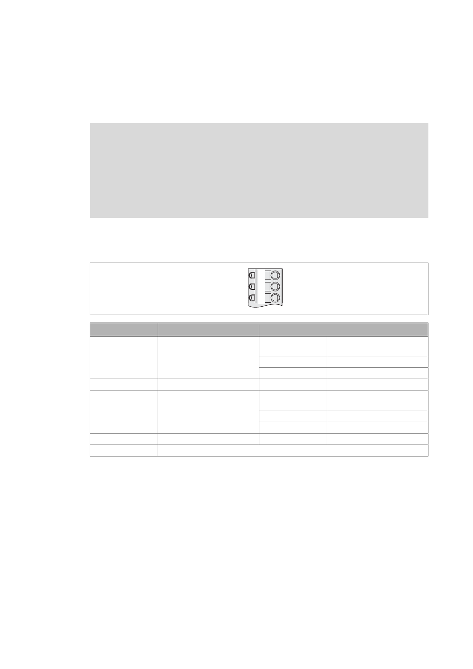
Terminal
Use
Electrical data
X3/AO1
Voltage output 1
Level: -10 V ... +10 V
(max. 2 mA)
Resolution: 11 bits + sign
Scaling: ±2
30
≡ ±10 V
Conversion rate: 1 kHz
X3/AO2
Voltage output 2
Level: -10 V ... +10 V
(max. 2 mA)
Resolution: 11 bits + sign
Scaling: ±2
30
≡ ±10 V
Conversion rate: 1 kHz
X3/GA
Reference potential (analog ground)
GA
AO1
AO2
X3