2 effect of c01130 on the sync phase position, 9"can on board" system bus – Lenze 9400 User Manual
Page 313
Lenze · Servo-Inverter 9400 HighLine · Reference manual · DMS 10.0 EN · 11/2013 · TD05/06
313
9
"CAN on board" system bus
9.6
Process data transfer
_ _ _ _ _ _ _ _ _ _ _ _ _ _ _ _ _ _ _ _ _ _ _ _ _ _ _ _ _ _ _ _ _ _ _ _ _ _ _ _ _ _ _ _ _ _ _ _ _ _ _ _ _ _ _ _ _ _ _ _ _ _ _ _
Sync application cycle
This parameter influences the effect of the sync phase position (
) with regard to the instant
of acceptance of the synchronous PDOs by the application or the instant of transmission of the
synchronous PDOs to the system bus.
The following applies to software versions lower than V3.0:
• The sync application cycle is permanently set to 1000 μs.
• The resulting PDO delay can be calculated with the following formula taking into consideration
an internal processing time of 150 s: PDO delay= (sync cycle time - sync phase position + 150 μs)
modulo 1000
The following applies from software version V3.0:
• The sync application cycle can be set in
. The set value is automatically rounded down to
full 1000 μs.
• The resulting PDO delay can be calculated with the following formula taking into consideration
an internal processing time of 150 s: PDO delay= (sync cycle time - sync phase position + 150 μs)
9.6.5.2
Effect of C01130 on the sync phase position
Note!
If the sync application cycle in
is set higher than the sync cycle time (
the behaviour is undefined. The same applies if the sync phase position (
) is set
higher than the sync cycle time (
).
Usually, no synchronous PDOs are then applied to the system bus anymore.
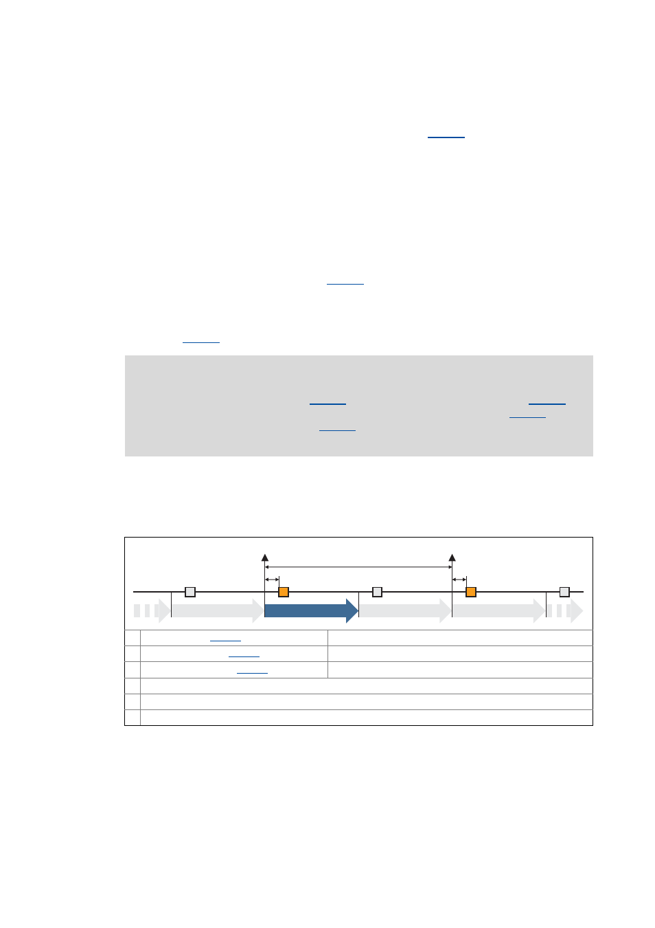
Example 1:
Sync cycle time (
)
= 2000 μs
Sync phase position (
)
= 0 μs
Sync application cycle (
)
= 1000 μs
Instant of acceptance/transmission of synchronous PDOs
Inactive instant of acceptance
n Device cycle
0
1
0
1
150 µs
n-1
1
150 µs
n
n+1
n+2
SYNC
SYNC