2 optimising the control mode, Optimising the control mode, The chapter – Lenze 9400 User Manual
Page 188: 5motor interface
5
Motor interface
5.6
V/f control (VFCplus)
188
Lenze · Servo-Inverter 9400 HighLine · Reference manual · DMS 10.0 EN · 11/2013 · TD05/06
_ _ _ _ _ _ _ _ _ _ _ _ _ _ _ _ _ _ _ _ _ _ _ _ _ _ _ _ _ _ _ _ _ _ _ _ _ _ _ _ _ _ _ _ _ _ _ _ _ _ _ _ _ _ _ _ _ _ _ _ _ _ _ _
5.6.2
Optimising the control mode
The "optimisation steps" given in the following table serve to further optimise the control behaviour
of the V/f control and adjust it to the concrete application.
• Detailed information on the individual steps can be found in the following subchapters.
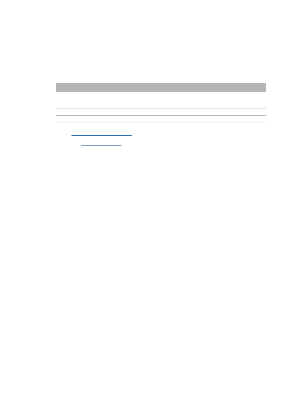
Optimisation steps
1.
Defining a user-defined V/f characteristic
• Individual adjustment of the motor magnetisation to the concrete application if linear and square-law
characteristics are not suitable.
2.
Parameterising slip compensation
3.
Parameterising oscillation damping
4. When the flying restart function is used: Optimise flying restart process.
Flying restart function ( 209)
5.
Optimising the current controller
• Only required if one of the following functions is used:
•
Voltage vector control ( 186)
•
Flying restart function ( 209)
•
6. Save »Engineer« project.