Mode 13: negative direction to limit switch, 11 basic drive functions – Lenze 9400 User Manual
Page 437
Lenze · Servo-Inverter 9400 HighLine · Reference manual · DMS 10.0 EN · 11/2013 · TD05/06
437
11
Basic drive functions
11.6
Homing
_ _ _ _ _ _ _ _ _ _ _ _ _ _ _ _ _ _ _ _ _ _ _ _ _ _ _ _ _ _ _ _ _ _ _ _ _ _ _ _ _ _ _ _ _ _ _ _ _ _ _ _ _ _ _ _ _ _ _ _ _ _ _ _
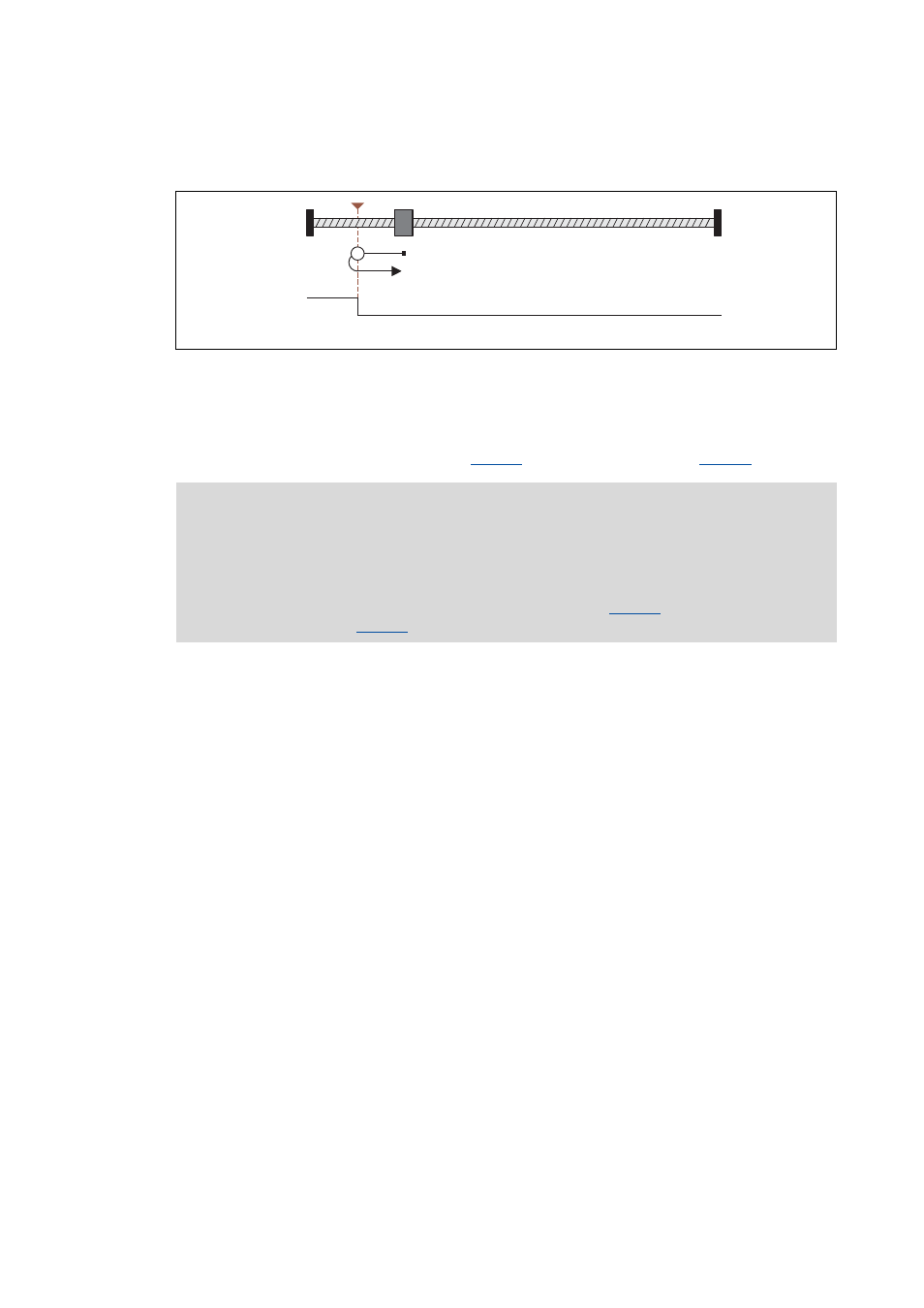
Mode 13: negative direction to limit switch
Procedure:
1. Movement in negative direction with profile data set 1.
2. Positive edge of the travel range limit switch sets reference.
3. Absolute positioning to target position (
) with profile data set 2 (if
= "0").
Negative travel range limit switch
Note!
The load machine can also leave the travel range limit switch. There follows a return to
the home position that was set with the positive edge of the travel range limit switch.
• It is possible that, as a result, the machine will remain on an operated limit switch.
• Therefore it is recommended to set a target position (
) that is unequal to the
home position (
) to release the activated limit switch again.
1
0