1 defining a user-defined v/f characteristic, Defining a user-defined v/f, Characteristic ( 189) – Lenze 9400 User Manual
Page 189: Defining a user-defined v/f characteristic, 5motor interface
Lenze · Servo-Inverter 9400 HighLine · Reference manual · DMS 10.0 EN · 11/2013 · TD05/06
189
5
Motor interface
5.6
V/f control (VFCplus)
_ _ _ _ _ _ _ _ _ _ _ _ _ _ _ _ _ _ _ _ _ _ _ _ _ _ _ _ _ _ _ _ _ _ _ _ _ _ _ _ _ _ _ _ _ _ _ _ _ _ _ _ _ _ _ _ _ _ _ _ _ _ _ _
5.6.2.1
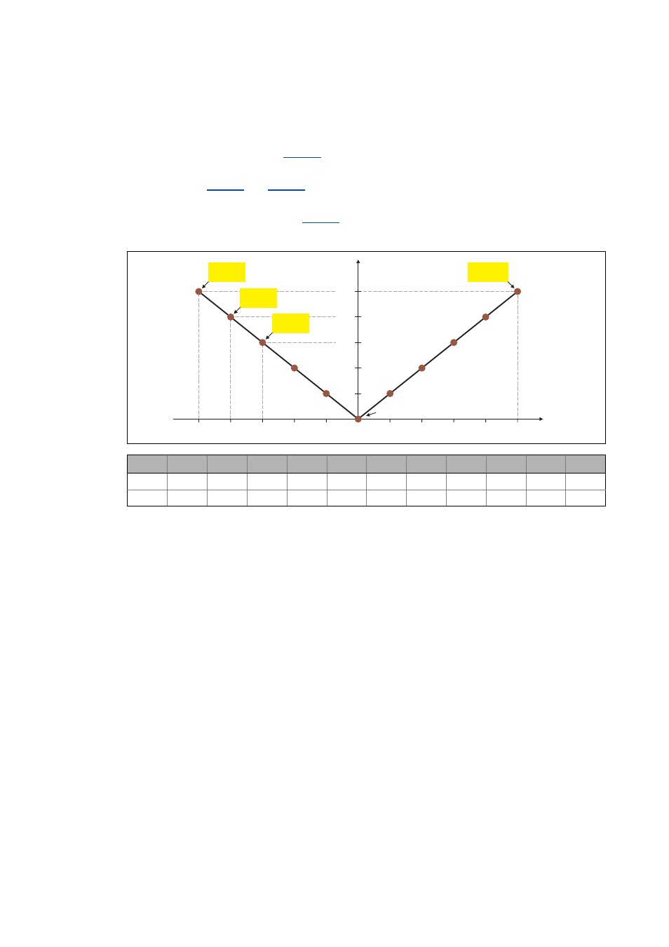
Defining a user-defined V/f characteristic
To individually adjust the motor magnetisation to the real application, a user-definable
characteristic can be selected in
if the linear and square-law characteristic are not suitable.
• The interpolation points (voltage/frequency values) of this characteristic are selected via the 11
subcodes of
and
.
• If less interpolation points are required, the interpolation points that are not needed have to be
deactivated via the subcodes of
.
• In the Lenze setting the 11 interpolation points represent a linear characteristic:
[5-18] User-definable characteristic (Lenze setting)
P1
P2
P3
P4
P5
P6
P7
P8
P9
P10
P11
V
400 V
320 V
240 V
160 V
80 V
0 V
80 V
160 V
240 V
320 V
400 V
f
-50 Hz
-40 Hz
-30 Hz
-20 Hz
-10 Hz
0 Hz
10 Hz
20 Hz
30 Hz
40 Hz
50 Hz
U [V]
160
0
f [Hz]
240
320
400
10
20
30
40
50
-50
-40
-30
-20
-10
80
C00952/1
C00953/1
C00952/2
C00953/2
C00952/3
C00953/3
C00952/11
C00953/11
P1
P2
P3
P4
P5
P7
P6
P8
P9
P10
P11