88 8 r, 2h 3 o – Lenze 8400 User Manual
Page 559
Lenze · 8400 protec HighLine · Reference manual · DMS 3.0 EN · 03/2013 · TD05
559
9
Diagnostics & error management
9.3
Drive diagnostics via the integrated 7-segment display
_ _ _ _ _ _ _ _ _ _ _ _ _ _ _ _ _ _ _ _ _ _ _ _ _ _ _ _ _ _ _ _ _ _ _ _ _ _ _ _ _ _ _ _ _ _ _ _ _ _ _ _ _ _ _ _ _ _ _ _ _ _ _ _
Manual operation display (in preparation)
If the controller is changed over to the manual operation mode using the operator button, "rc" is
displayed (remote control):
• When it is changed over between CCW and CW rotation using the operator button, the output
frequency of the motor in CW rotation is displayed without sign and in CCW rotation with
minus sign.
• Example: "-21.3" = motor rotates in CCW rotation with an output frequency of 21.3 Hz.
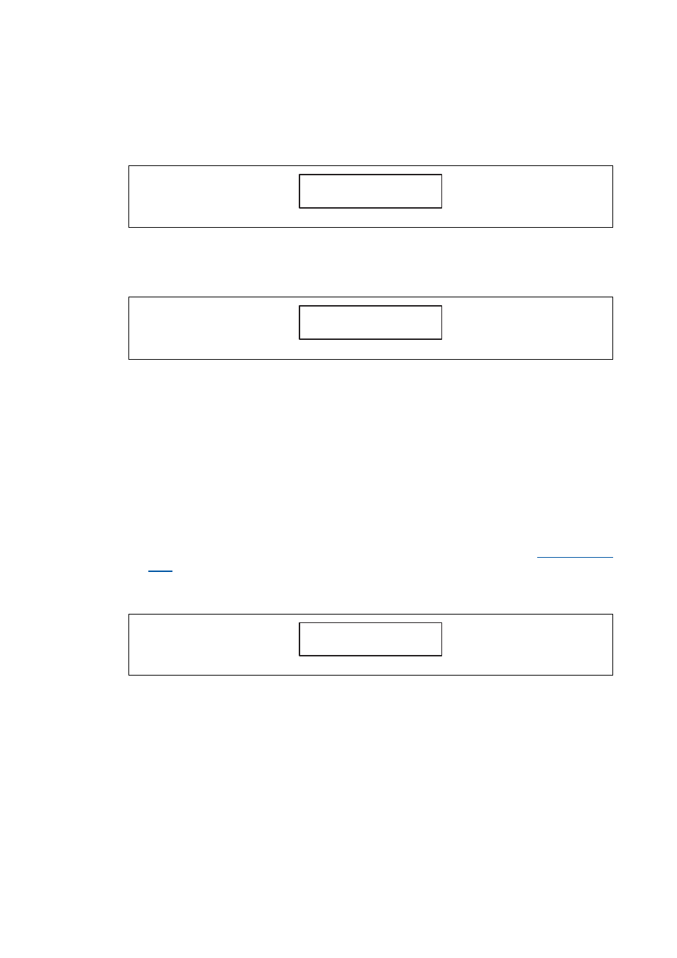
Message display
If warnings or errors exist, these are shown in blinking mode.
• If several errors exist, the active status determining error is displayed and all further errors will
only be entered into the logbook.
The messages are structured as follows:
• The character in position S5 indicates the device number if several subordinated device are
connected to the controller via the fieldbus interface, for example:
• "1" = 8400 protec controller (master)
• "2" = 8400 protec controller (slave 1 to node address 2)
• "3" = 8400 protec controller (slave 2 to node address 3), etc.
• The characters in positions S1 to S4 indicate the abbreviated warning or error.
• Example: "2 OH3" = In case of the device on node address 2, the warning "OH3: Motor
temperature (X21) triggered" is active.
8
8
8
8 8
r
.
.
.
.
.
S1
S2
S3
S4
S5
c
8
8
8
8 8
.
.
.
.
.
S1
S2
S3
S4
S5
- 2 1 3
8
8
8
8 8
.
.
.
.
.
S1
S2
S3
S4
S5
2
H 3
O