5motor control (mctrl) – Lenze 8400 User Manual
Page 279
Lenze · 8400 protec HighLine · Reference manual · DMS 3.0 EN · 03/2013 · TD05
279
5
Motor control (MCTRL)
5.13
Braking operation/brake energy management
_ _ _ _ _ _ _ _ _ _ _ _ _ _ _ _ _ _ _ _ _ _ _ _ _ _ _ _ _ _ _ _ _ _ _ _ _ _ _ _ _ _ _ _ _ _ _ _ _ _ _ _ _ _ _ _ _ _ _ _ _ _ _ _
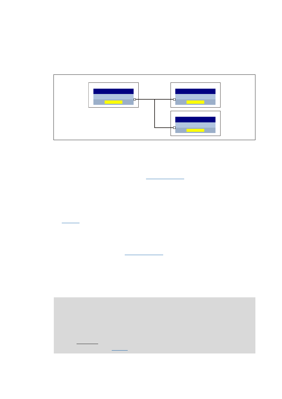
• The "brake chopper slaves" have the bBrakeChopperActive status signal received from the "brake
chopper master" connected to the bBrakeChopperOn control input.
• If the internal brake transistor of the "brake chopper master" is switched on, the internal brake
transistors of the "brake chopper slaves" are switched on at the same time.
[5-33] Functional principle of the "Brake chopper master-slave operation" (simplified representation)
Procedure
1. Assign the role of the "brake chopper master" to one of the controllers of the DC-bus system.
2. Adapt the function block interconnection for the "brake chopper master" so that the
bBrakeChopperActive status signal of the
SB is provided to the other
controllers for controlling the internal brake chopper.
• The bBrakeChopperActive signal can e.g. be output via port block to the fieldbus or via digital
output.
• A free output of the application block can be used to transfer the signal from application level
to I/O level.
3. Configure all other controllers of the DC-bus system as "brake chopper slaves". Select "1: Yes" in
for these controllers.
• With this setting, the brake chopper is not controlled via the DC-bus voltage anymore. Its
control now depends on the bBrakeChopperOn control signal.
4. Adapt the function block interconnection for the "brake chopper slaves" so that the
bBrakeChopperActive signal received from the "brake chopper master" is connected to the
bBrakeChopperOn input of the
SB.
• Depending on the output at the "brake chopper master", the signal must be read in e.g. via
port block or digital input.
• A free input of the application block can be used to transfer the signal from I/O level to
application level.
• If the digital inputs/outputs are used for transmitting the signal, they must be connected
electrically accordingly.
%UDNHFKRSSHUPDVWHU
E%UDNH&KRSSHU$FWLYH
/6B0RWRU,QWHUIDFH
E%UDNH&KRSSHU2Q
/6B0RWRU,QWHUIDFH
&
&
%UDNHFKRSSHUVODYHV
E%UDNH&KRSSHU2Q
/6B0RWRU,QWHUIDFH
&
Note!
If the brake chopper master-slave operation is activated, plausibility monitoring is
carried out in the "brake chopper slaves":
• The brake transistor can only be switched on via the bBrakeChopperOn control signal
if the DC-bus voltage is greater than the brake chopper threshold minus 40 V
DC
.
• Exception: From a mains voltage of 513 V
AC
(or 725 V
DC
) and a mains voltage of 480
, the plausibility monitoring is not effective anymore.