5motor control (mctrl) – Lenze 8400 User Manual
Page 283
Lenze · 8400 protec HighLine · Reference manual · DMS 3.0 EN · 03/2013 · TD05
283
5
Motor control (MCTRL)
5.14
Monitoring
_ _ _ _ _ _ _ _ _ _ _ _ _ _ _ _ _ _ _ _ _ _ _ _ _ _ _ _ _ _ _ _ _ _ _ _ _ _ _ _ _ _ _ _ _ _ _ _ _ _ _ _ _ _ _ _ _ _ _ _ _ _ _ _
Adjustment of the motor utilisation meter
The motor utilisation meter for indicating the motor load in
begins to count when the
apparent motor current (
) is greater than the motor overload setting (
).
The Motor overload setting (
) is calculated as follows:
• If you reduce
starting from the calculated value, the motor utilisation meter will already
be counted up before the rated overload threshold is reached.
• If you increase
starting from the calculated value, the motor utilisation meter will not
be counted up until the rated overload threshold is reached.
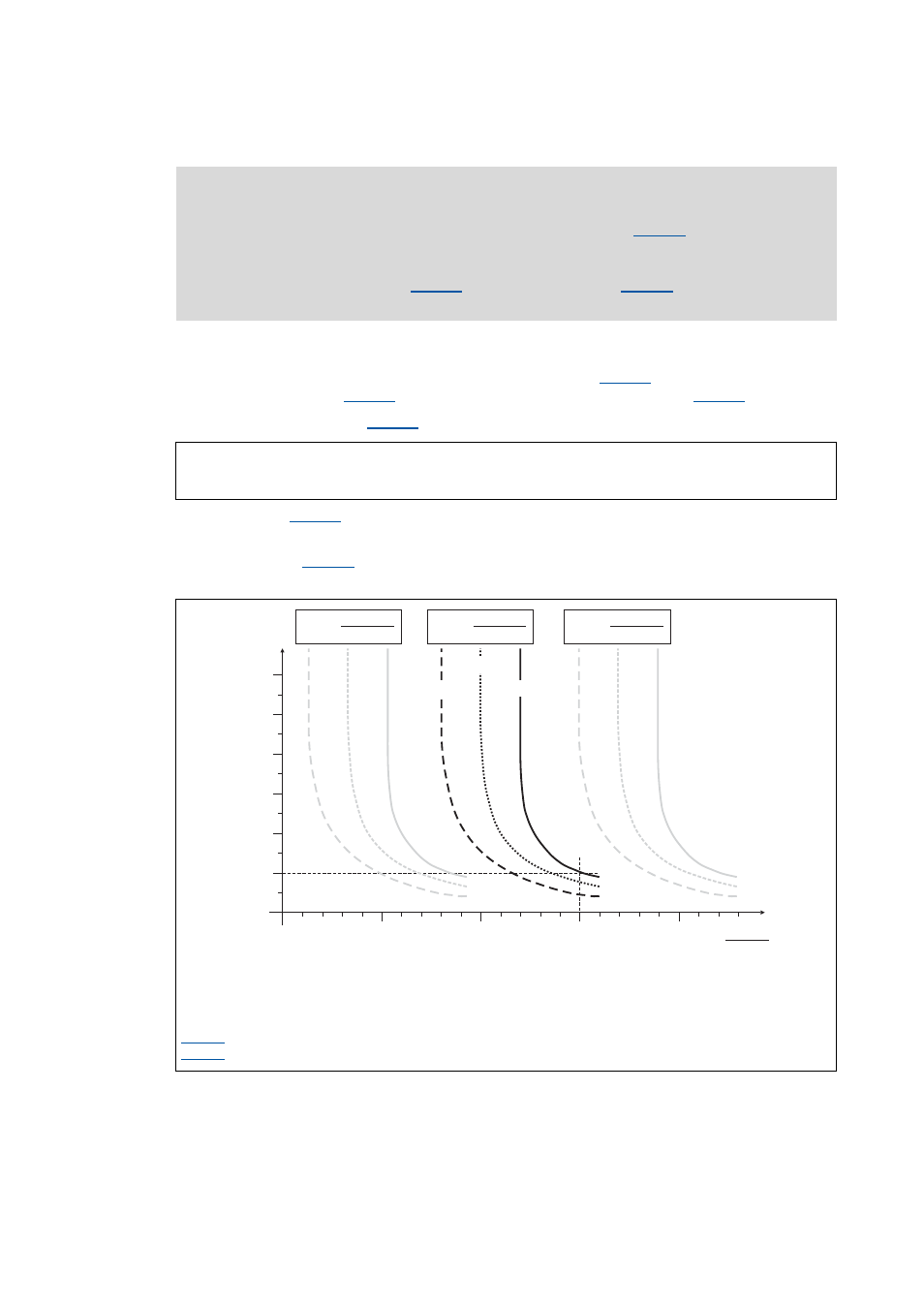
[5-34] Tripping characteristic of the I
2
xt monitoring
Note!
From version 07.00.00
, the thermal motor load displayed in
initialised when the device is connected to the mains, optionally using a fixed value or
the value used last at the time when the device was switched off. The desired
initialisation is selected in
, the behaviour
remains unchanged (no initialisation).
f: Output frequency
t: Release time
I
N
: Rated current of drive controller at a switching frequency of f = 8 kHz
I
r
: Rated motor current (see nameplate of motor)
: Apparent motor current
: Motor overload setting
C00120
Rated motor current (C00088)
Rated device current (C00098)
------------------------------------------------------------------------------
100 %
⋅
=
60
180
240
300
360
t [s]
0.5
0
0
1.0
1.5
2.0
C00054
I
r
120
f = 0 Hz
f = 20 Hz
f > 40 Hz
I x 100 %
I
r
N
C00120 <
I x 100 %
I
r
N
C00120 =
I x 100 %
I
r
N
C00120 >