1 parameterising analog input, Parameterising analog input, Parameterising analog input ( 327) – Lenze 8400 User Manual
Page 327: 6i/o terminals
Lenze · 8400 protec HighLine · Reference manual · DMS 3.0 EN · 03/2013 · TD05
327
6
I/O terminals
6.2
Analog terminals
_ _ _ _ _ _ _ _ _ _ _ _ _ _ _ _ _ _ _ _ _ _ _ _ _ _ _ _ _ _ _ _ _ _ _ _ _ _ _ _ _ _ _ _ _ _ _ _ _ _ _ _ _ _ _ _ _ _ _ _ _ _ _ _
6.2.1
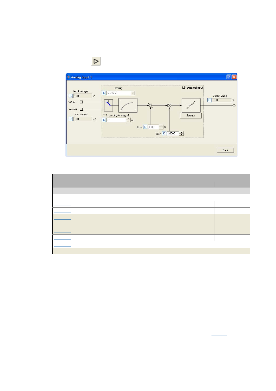
Parameterising analog input
By clicking on the
button on the Terminal assignment tab, you reach the parameterising
dialog for the analog input:
Short overview of the parameters for the analog input:
Using current input A1I
In the Lenze setting, voltage signals in the 0 ... +10 V range are evaluated via the analog input A1U.
If current signals are to be detected via the input A1I instead, the selection "1: 0...20 mA" or "2:
4...20mA" must be set in
.
Tip!
By selecting "2: 4...20mA", you can implement a 4 ...20 mA current loop, e.g. for stipulation
of the speed setpoint.
Open-circuit monitoring
In the case of configuration as a 4 ... 20 mA current loop, the fault response set in
takes place
in the event of a wire breakage (Lenze setting: "TroubleQuickStop").
Parameter
Info
Lenze setting
Value Unit
Analog input 1
AIN1: Config.
0: 0 V .... + 10 V
AIN1: Offset
0.00 %
AIN1: Gain
1.0000
AIN1: Input voltage
- V
AIN1: Input current
- mA
AIN1: Output value (to application)
- %
PT1 rounding AnalogIn1
10 ms
Resp. to open circuit AIN1
3: TroubleQuickStop
Highlighted in grey = display parameter