1 device overload monitoring (ixt), 2 motor load monitoring (i2xt), Device overload monitoring (ixt) – Lenze 8400 User Manual
Page 282: Motor load monitoring (i2xt), 5motor control (mctrl), Stop
5
Motor control (MCTRL)
5.14
Monitoring
282
Lenze · 8400 protec HighLine · Reference manual · DMS 3.0 EN · 03/2013 · TD05
_ _ _ _ _ _ _ _ _ _ _ _ _ _ _ _ _ _ _ _ _ _ _ _ _ _ _ _ _ _ _ _ _ _ _ _ _ _ _ _ _ _ _ _ _ _ _ _ _ _ _ _ _ _ _ _ _ _ _ _ _ _ _ _
5.14.1
Device overload monitoring (Ixt)
displays the device utilisation (ixt) in [%] in different time intervals:
• If the device utilisation reaches the switch-off threshold set in
:
• The "Fault" error response is returned.
• The "
" error message will be entered into the Logbook.
• The bMctrlIxtOverload status output of the
TRUE.
5.14.2
Motor load monitoring (I2xt)
The Inverter Drives 8400 are provided with a simple, sensorless, thermal I
2
xt motor monitoring of
self-ventilated standard motors which is based on a mathematical model.
•
displays the calculated motor load in [%].
• If the calculated motor load reaches the motor load setting (
• The error response set in
will be carried out (Lenze setting: "Warning").
• The "
" error message will be entered into the Logbook.
• The bMctrlI2xtOverload status output of the
system block will be set to
TRUE.
• A setting of
= "0: No Reaction" deactivates the monitoring.
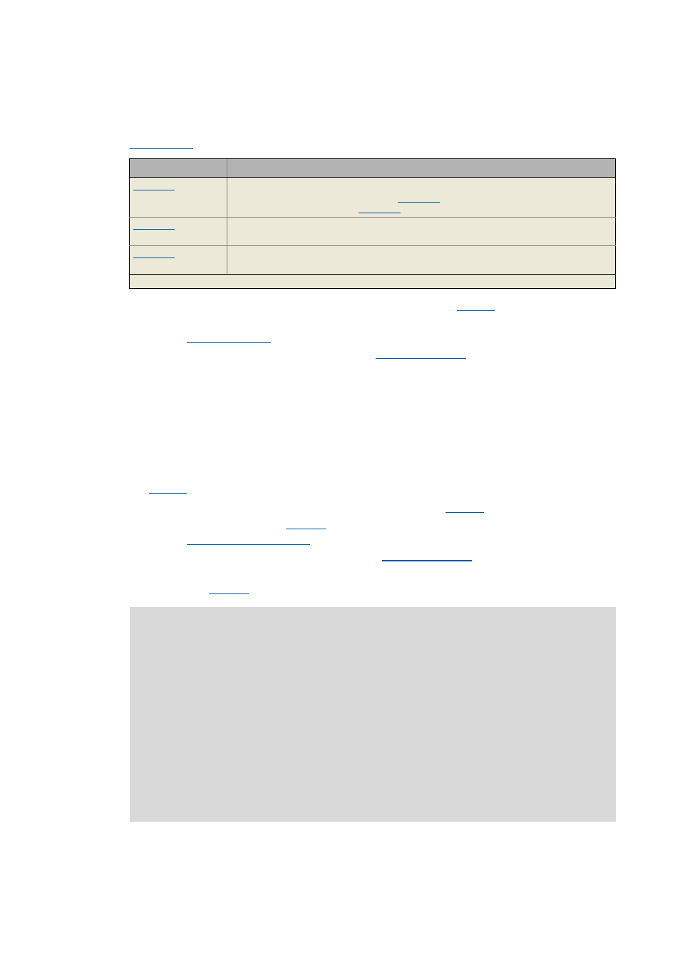
Parameter
Info
Device utilisation (Ixt)
• Maximum value of pulse utilisation (
and permanent utilisation (
Device utilisation (Ixt) 15s
• Pulse utilisation over the last 15 seconds (only for loads >160 %).
Device utilisation (Ixt) 3 min
• Permanent utilisation over the last 3 minutes.
Highlighted in grey = display parameter
Stop!
The I
2
xt motor monitoring does not present full motor protection! As the motor
utilisation calculated in the thermal motor model is lost after mains switching, for
instance the following operating states cannot be measured correctly:
• Restarting (after mains switching) of a motor that is already very hot.
• Change of the cooling conditions (e.g. cooling air flow interrupted or too warm).
A full motor protection requires additional measures as e.g. the evaluation of
temperature sensors that are located directly in the winding or the use of thermal
contacts.
For the installation according to UL or UR, the safety instructions provided in the
hardware manual must be observed! Among other things, the activation of the motor
overload monitoring (I2xt) is required here.