65 2 8 f – Lenze 8400 User Manual
Page 558
9
Diagnostics & error management
9.3
Drive diagnostics via the integrated 7-segment display
558
Lenze · 8400 protec HighLine · Reference manual · DMS 3.0 EN · 03/2013 · TD05
_ _ _ _ _ _ _ _ _ _ _ _ _ _ _ _ _ _ _ _ _ _ _ _ _ _ _ _ _ _ _ _ _ _ _ _ _ _ _ _ _ _ _ _ _ _ _ _ _ _ _ _ _ _ _ _ _ _ _ _ _ _ _ _
Automatic display
In this mode, five parameters can be displayed in a row.
• The selection key T1 serves to browse the parameters in ascending order. After the status
value S5, it starts anew with status value S1.
• The parameters to be displayed as status values S1 ... S5 in the display can be configured using
the »Engineer« (in preparation).
• In the Lenze setting, the following status values are displayed:
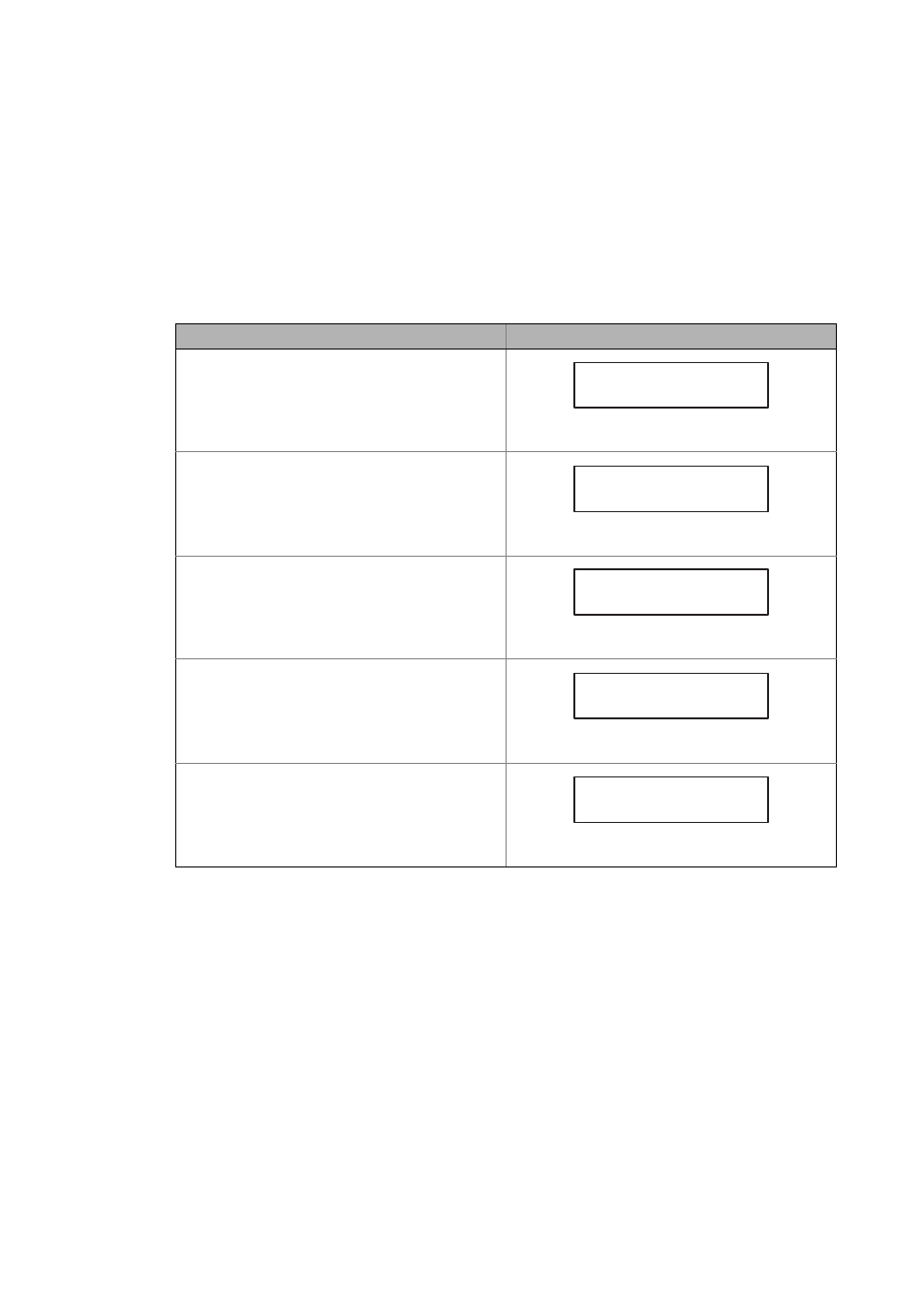
Status value
Example
S1: Motor output frequency in [Hz]
• The output frequency is displayed as a function of the
direction of rotation, i.e. in case of CCW rotation, a
minus sign is displayed.
• Display area: ±999 Hz
"F 256" = output frequency 256 Hz
S2: Actual current value in [0.1 A]
"I 25.6" = actual current value 25.6 A
S3: Device utilisation in [%]
"P 156" = Device utilisation 156 %
S4: Motor voltage in [V]
"u 358" = Motor voltage 358 V
S5: DC-bus voltage in [V]
"U 558" = DC-bus voltage 558 V
6
5
2
8
F
.
.
.
.
.
S1
S2
S3
S4
S5
8
8
8
2 6
5
8 8
I
.
.
.
.
.
S1
S2
S3
S4
S5
8
8
8
1 6
5
8 8
P
.
.
.
.
.
S1
S2
S3
S4
S5
8
8
8
3 5
8 8
u
.
.
.
.
.
S1
S2
S3
S4
S5
8
8
8
5 5
8 8
U
.
.
.
.
.
S1
S2
S3
S4
S5