3 activation of the modulo measuring system, Activation of the modulo measuring system, 8basic drive functions (mck) – Lenze 8400 User Manual
Page 470
8
Basic drive functions (MCK)
8.4
Basic settings
470
Lenze · 8400 protec HighLine · Reference manual · DMS 3.0 EN · 03/2013 · TD05
_ _ _ _ _ _ _ _ _ _ _ _ _ _ _ _ _ _ _ _ _ _ _ _ _ _ _ _ _ _ _ _ _ _ _ _ _ _ _ _ _ _ _ _ _ _ _ _ _ _ _ _ _ _ _ _ _ _ _ _ _ _ _ _
8.4.1.3
Activation of the modulo measuring system
This function extension is available from version 06.00.00!
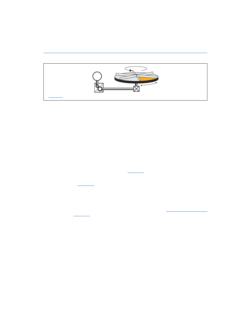
The Modulo measuring system is also called "rotary table application".
[8-12] Example: Rotary table application
• The measuring system is repeated.
• If the set cycle is exceeded, a defined overflow occurs.
• In a rotative system, the cycle usually corresponds to one revolution or tool distance.
• The home position must be known for positioning.
• Exception: Positioning mode relative (TP) and continuous (TP)
• Software limit positions are not effective.
• Absolute targets can be approached by exceeding the measuring system limit, e.g. from 10° via
0° to 350°.
Activating the Modulo measuring system
The Modulo system is activated by setting a cycle (
) > 0 units.
• The cycle can be set if the controller is enabled.
• When the cycle (
) is set to 0 units (Lenze setting), the traversing range is unlimited
(classical measuring system).
Generation of the Modulo measuring system
When the Modulo measuring system is active, it is displayed internally via an integrator. The
Modulo position is provided at the dnPosSet_p process output of the SB
and displayed in
. When the Modulo measuring system is not active, the continuous
(dnPosSetValue_p) setpoint position is output instead.
: Cycle
M