1 using di1(5) and di2(6) as digital inputs, Using di1(5) and di2(6) as digital inputs, 6i/o terminals – Lenze 8400 User Manual
Page 306
6
I/O terminals
6.1
Digital terminals
306
Lenze · 8400 protec HighLine · Reference manual · DMS 3.0 EN · 03/2013 · TD05
_ _ _ _ _ _ _ _ _ _ _ _ _ _ _ _ _ _ _ _ _ _ _ _ _ _ _ _ _ _ _ _ _ _ _ _ _ _ _ _ _ _ _ _ _ _ _ _ _ _ _ _ _ _ _ _ _ _ _ _ _ _ _ _
6.1.1.1
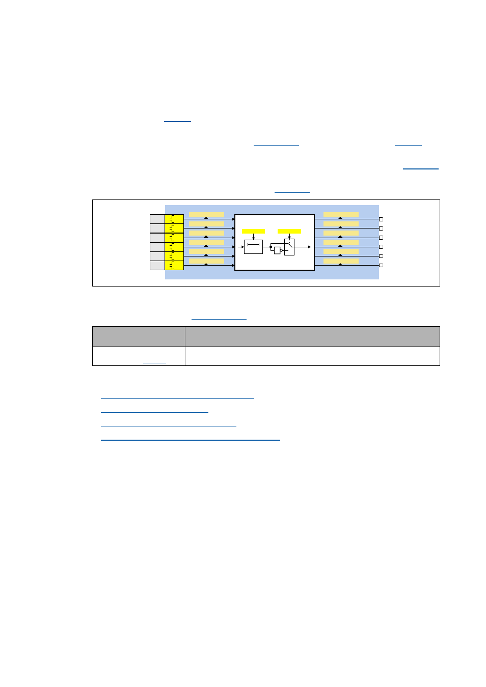
Using DI1(5) and DI2(6) as digital inputs
Function assignment 0: DI1(5)=In / DI2(6)=In
With this setting in
, the digital input terminals have been configured as "normal" digital
inputs.
• For each digital input, the debounce time (
) and the terminal polarity (
) can
be set individually.
• The current terminal level at the input of the internal processing function is shown in
in bit-coded form.
• The output level for the application is shown in
in bit-coded form.
Internal interfaces to the application
• Relevant outputs at the
system block:
Related topics:
Using DI1(5) and DI2(6) as frequency inputs
Using DI1(5) as counting input
Reconfiguring DI3(4) to output DO1(2)
Internal interfaces | System block "LS_DigitalInput"
Output
DIS code | data type
Value/meaning
bIn1 ... bIn6
| BOOL
Digital input DI1 ... DI6
&%LW
E,Q
E,Q
E,Q
E,Q
E,Q
E,Q
&
W
&[
&%LW
&%LW
&%LW
&%LW
&%LW
&%LW
&%LW
&%LW
&%LW
',
',
',
',
',
',
&%LW
&%LW