5 masking out touch probe signals, Masking out touch probe signals 2, 18 function library – Lenze 8400 User Manual
Page 1272
18
Function library
18.1
Function blocks | L_DFSET_1
1272
Lenze · 8400 protec HighLine · Reference manual · DMS 3.0 EN · 03/2013 · TD05
_ _ _ _ _ _ _ _ _ _ _ _ _ _ _ _ _ _ _ _ _ _ _ _ _ _ _ _ _ _ _ _ _ _ _ _ _ _ _ _ _ _ _ _ _ _ _ _ _ _ _ _ _ _ _ _ _ _ _ _ _ _ _ _
Compensation process
At the input of the second set or actual touch probe pulse, the difference between master and slave
position is detected which is then provided via the nSpeedSetOut_v speed output and equivalently
as position at .
• The compensation process directly takes place by defining the increments/ms set in
In order to prevent a jerk in speed, the Lenze setting provides a rounding via polynomial. By
resetting bit 1 in
, this rounding can be deactivated if required.
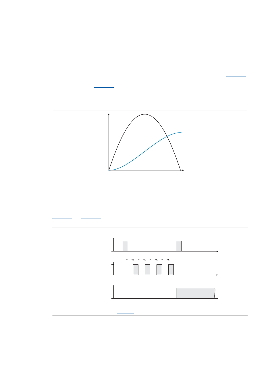
• The following illustration shows a compensating process after the marks have been detected.
The speed is added here as a parabola to the line speed. (The scaling in this diagram does not
correspond to reality)
[18-39] Compensating movement
18.1.73.5 Masking out touch probe signals
When passing-through material is used, e.g. printed foil, touch probe initiators may respond several
times per cycle. For suppressing such "interference pulses", count values can be selected in
that are decremented when the touch probe pulse has been received. Only
when the counter content is "0", the synchronisation will be enabled.
[18-40] Synchronisation process in the modes 1, 2, 10, 11, 12 with a masking out of the touch probe pulses
nSpeedSetOut_v
dnPosDiffOut_p
t
v
Synchronisation mode = 1, 2, 10, 11, 12
Divisor for setpoint zero pulse (
) = 0
Divisor for actual value zero pulse (
) = 4
TRUE
FALSE
bAck
t
t
TRUE
FALSE
bSetTPReceived
t
TRUE
FALSE
bActTPReceived
3
2
1
0
4
0