3 motor mounting direction, 4 feedback configuration, Motor mounting direction – Lenze E94AxPExxxx User Manual
Page 83: Feedback configuration, 5drive interface
Lenze · 9400 Servo PLC· Reference manual · DMS 4.0 EN · 11/2013 · TD05/06
83
5
Drive interface
5.1
Machine parameters
_ _ _ _ _ _ _ _ _ _ _ _ _ _ _ _ _ _ _ _ _ _ _ _ _ _ _ _ _ _ _ _ _ _ _ _ _ _ _ _ _ _ _ _ _ _ _ _ _ _ _ _ _ _ _ _ _ _ _ _ _ _ _ _
5.1.3
Motor mounting direction
Depending on the motor mounting position, you can carry out an inversion of the direction of
rotation via the Motor mounting direction list field (
), if required:
•
= "0": Clockwise rotating motor ≡ positive machine direction.
•
= "1": Counter-clockwise rotating motor ≡ positive machine direction.
5.1.4
Feedback configuration
In most cases the system only has one motor encoder, i.e. no separate position encoder is installed
on the load side. The motor position (angle of rotation) and motor speed are detected via the motor
encoder selected in
and converted with regard to the load side.
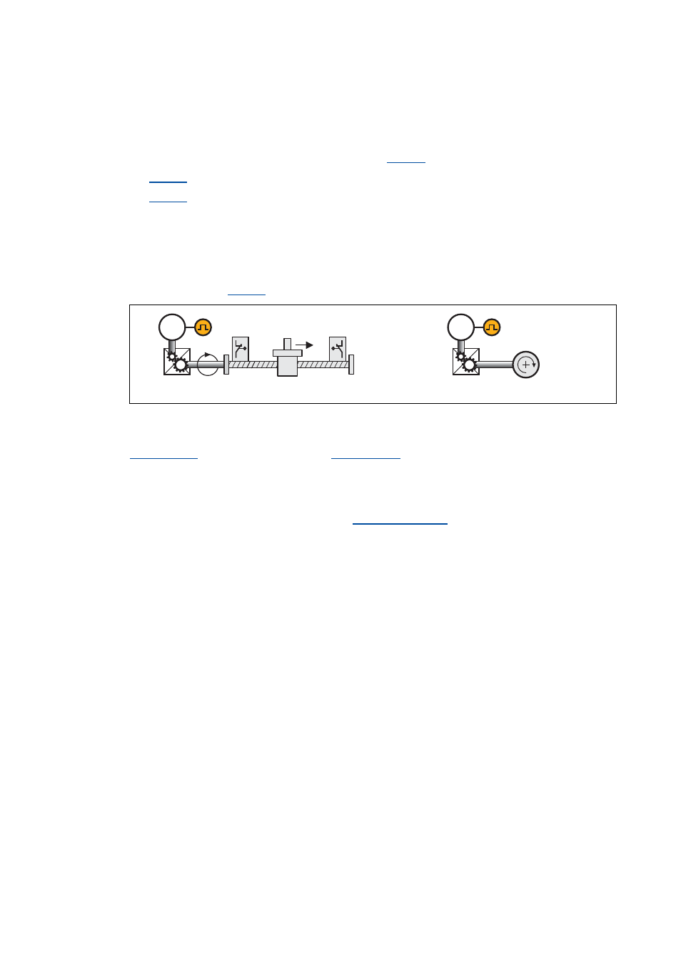
[5-4]
Schematic diagram - feedback with position encoder = motor encoder
The actual position and speed values on the machine side result from the conversion via the
on the motor side and the
.
Tip!
Detailed information on the parameterisation of the feedback systems for the motor
control can be found in the chapter "
Motor encoder
M
M