1 identifiers of the parameter data objects, 2 user data, 10 "can on board" system bus – Lenze E94AxPExxxx User Manual
Page 356
10
"CAN on board" system bus
10.7
Parameter data transfer
356
Lenze · 9400 Servo PLC· Reference manual · DMS 4.0 EN · 11/2013 · TD05/06
_ _ _ _ _ _ _ _ _ _ _ _ _ _ _ _ _ _ _ _ _ _ _ _ _ _ _ _ _ _ _ _ _ _ _ _ _ _ _ _ _ _ _ _ _ _ _ _ _ _ _ _ _ _ _ _ _ _ _ _ _ _ _ _
10.7.1
Identifiers of the parameter data objects
The identifiers for the parameter data objects SDO1 ... SDO10 in the Lenze setting result from the
basic identifier and the node address set in
.
Identifier (COB-ID) = basic identifier + node address (node ID)
• The basic identifiers of the SDOs are preset in the Lenze setting according to the "Predefined
Connection Set" of DS301 V4.02.
10.7.2
User data
Structure of the user data of the parameter data telegram
The following subchapters provide detailed information on user data.
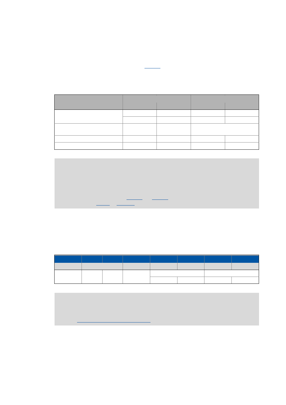
Parameter data object
Direction
Basic identifier
from device
to device
dec
hex
SDO1
(Parameter data channel 1)
1408
580
1536
600
SDO2 ... 10
(Parameter data channel 2 ... 10)
deactivated
Node guarding, heartbeat
1792
700
Boot-up
1792
700
Note!
Please observe that the parameter data channels 2 ... 10 are deactivated in the Lenze
setting.
The procedure for activating these parameter data channels is explained in the
description of parameters
and the description for the implemented
1st byte
2nd byte 3rd byte
4th byte
5th byte
6. byte
7th byte
8th byte
Command
Index
Subindex
Data 1
Data 2
Data 3
Data 4
LOW byte
HIGH
byte
LOW word
HIGH word
LOW byte
HIGH byte
LOW byte
HIGH byte
Note!
For the user data, the Motorola format is used.
Parameter data telegram examples