6motor interface, 8 parameterisable additional functions 252 – Lenze E94AxPExxxx User Manual
Page 252
6
Motor interface
6.8
Parameterisable additional functions
252
Lenze · 9400 Servo PLC· Reference manual · DMS 4.0 EN · 11/2013 · TD05/06
_ _ _ _ _ _ _ _ _ _ _ _ _ _ _ _ _ _ _ _ _ _ _ _ _ _ _ _ _ _ _ _ _ _ _ _ _ _ _ _ _ _ _ _ _ _ _ _ _ _ _ _ _ _ _ _ _ _ _ _ _ _ _ _
5. Set the gain Vp in
, which have been determined during
the adjustment with rated motor current (in this example "5 A"):
• Set
• Set
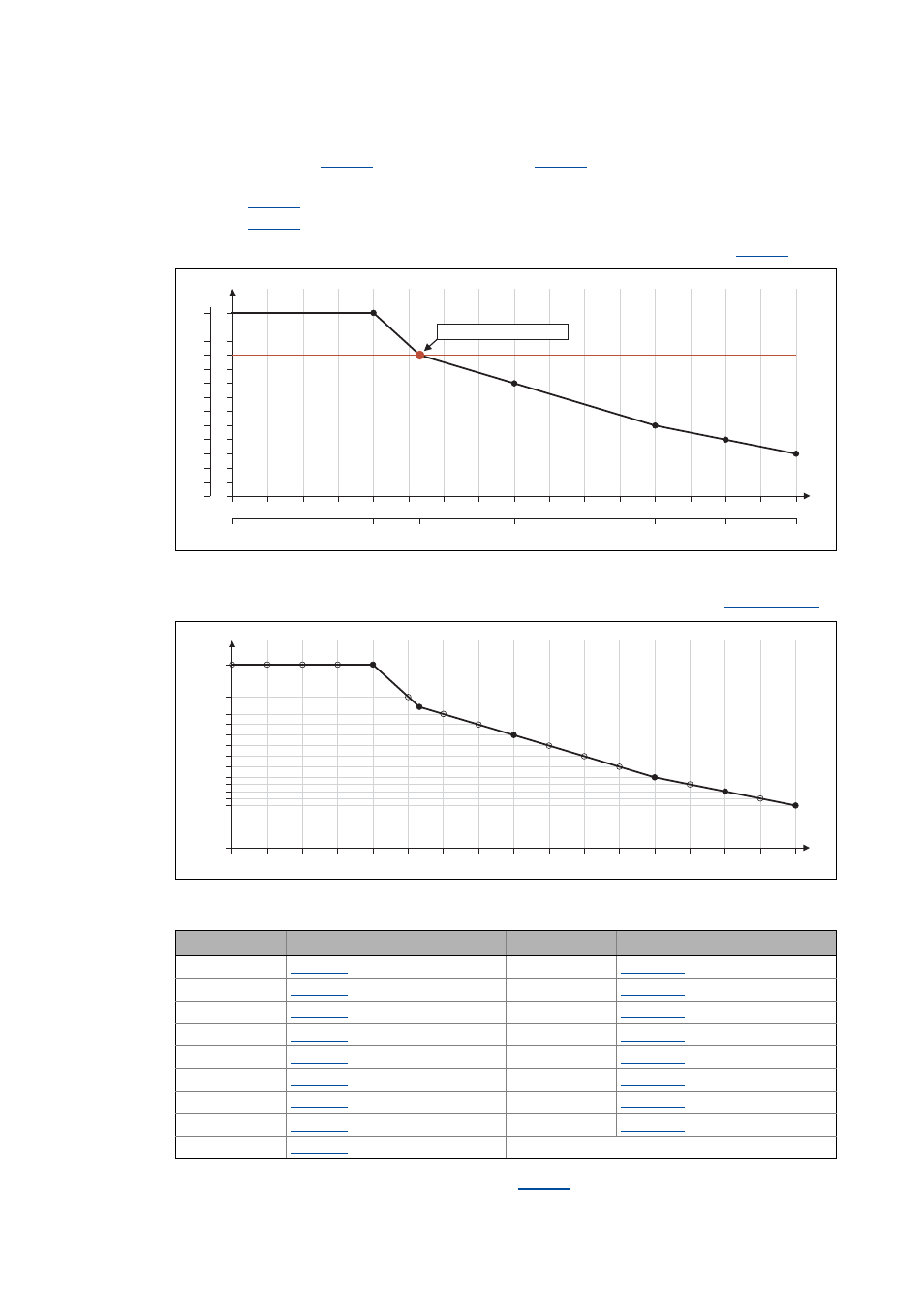
6. Scale the Vp values on the Y axis of the characteristic to the 100 % Vp setting in
[6-26] Scaling of the determined saturation characteristic to the "100 %" setting in C00075
7. Enter the Vp values in percent, which are placed on the interpolation point, in
:
[6-27] Grid point values of the saturation characteristic determined
8. Enter the maximum process current ("15 A") in
.
15 A
2
3
4
5
6
7
8
9
10
11
12
13
14
15
16
17
7.5 A
3.75 A
11.25 A
12.38 A
5 A
0
6.25
12.5
18.75
25
31.25
37.5
43.75
50
56.25
62.5
68.75
75
81.25
87.5
93.75
100
Vp [%]
0 A
0
1
2
3
4
5
6
7
8
9
10
11
12
13
0
10
20
30
40
50
60
70
80
90
100
110
120
130
C00075 = "10 V/A"
100 %
º
1
I
max
[%]
2
3
4
5
6
7
8
9
10
11
12
13
14
15
16
17
0
6.25
12.5
18.75
25
31.25
37.5
43.75
50
56.25
62.5
68.75
75
81.25
87.5
93.75
100
Vp [%]
30
40
57.5
65
72.5
80
87.5
95
107
130
50
45
35
0
1
I
max
[%]
Grid point Setting
Grid point Setting
1
= 130 %
10
= 72.5 %
2
= 130 %
11
= 65 %
3
= 130 %
12
= 57.5 %
4
= 130 %
13
= 50 %
5
= 130 %
14
= 45 %
6
= 107 %
15
= 40 %
7
= 95 %
16
= 35 %
8
= 87.5 %
17
= 30 %
9
= 80 %