1 adjustment of the pole position identification, Adjustment of the pole position identification, 6motor interface – Lenze E94AxPExxxx User Manual
Page 180: Stop
6
Motor interface
6.3
Adjusting motor and controller to each other
180
Lenze · 9400 Servo PLC· Reference manual · DMS 4.0 EN · 11/2013 · TD05/06
_ _ _ _ _ _ _ _ _ _ _ _ _ _ _ _ _ _ _ _ _ _ _ _ _ _ _ _ _ _ _ _ _ _ _ _ _ _ _ _ _ _ _ _ _ _ _ _ _ _ _ _ _ _ _ _ _ _ _ _ _ _ _ _
6.3.3.1
Adjustment of the pole position identification
The two procedures for
(PPI) described in the previous sections can be
adjusted to the respective machine and the prevailing moments of inertia by means of the
parameters described below.
Parameters for the pole position identification 360°
• The current amplitude can be adjusted proportionally in
• For large machines and high mass inertia values or for linear direct drives, the current
amplitude usually has to be increased.
• The Lenze setting "100 %" corresponds to the smaller of the two following values:
Note!
The two procedures for the pole position identification should give the same results. But,
due to e.g. friction, bearing forces and a trapezoidal field pattern, the results may differ.
A proportional increase of the current amplitude in
can counteract
this deviation.
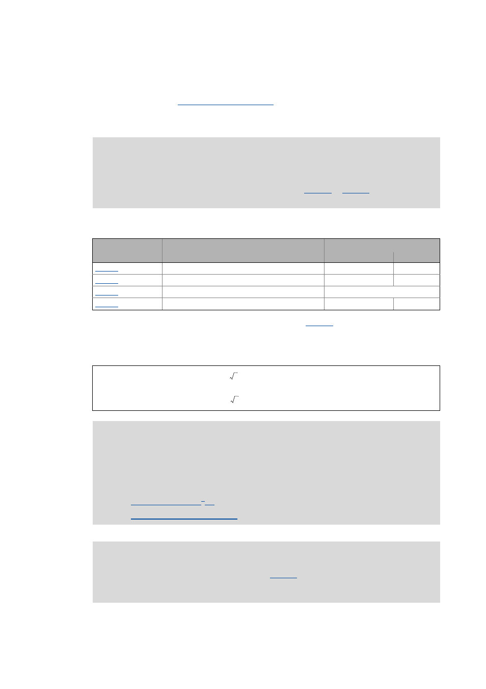
Parameter
Info
Lenze setting
Value Unit
PLI 360° current amplitude
100 %
PLI 360° ramp time
100 %
PLI 360° traversing direction
Clockwise rotating field
PolePosId 360° fault tol.
0 °
or
Stop!
If there is no temperature monitoring in the motor and/or the I
2
xt motor monitoring and
the maximum current monitoring are not parameterised correctly, the motor may be
permanently damaged when the current amplitude is set too high (e.g. to the maximum
value)!
Note!
If the current amplitude is set to 100 % in
>, the device utilisation (Ixt)
monitoring and/or one of the motor monitoring functions may respond and cause the
abort of the pole position identification.
2 Rated device current
⋅
2 Rated motor current
⋅