12 basic drive functions – Lenze E94AxPExxxx User Manual
Page 557
Lenze · 9400 Servo PLC· Reference manual · DMS 4.0 EN · 11/2013 · TD05/06
557
12
Basic drive functions
12.12
Brake control
_ _ _ _ _ _ _ _ _ _ _ _ _ _ _ _ _ _ _ _ _ _ _ _ _ _ _ _ _ _ _ _ _ _ _ _ _ _ _ _ _ _ _ _ _ _ _ _ _ _ _ _ _ _ _ _ _ _ _ _ _ _ _ _
Triggering the brake via the motor brake control module E94AZHX0051
The motor brake control module E94AZHX0051 does not include an additional 3-pole terminal for
the external control of the holding brake.
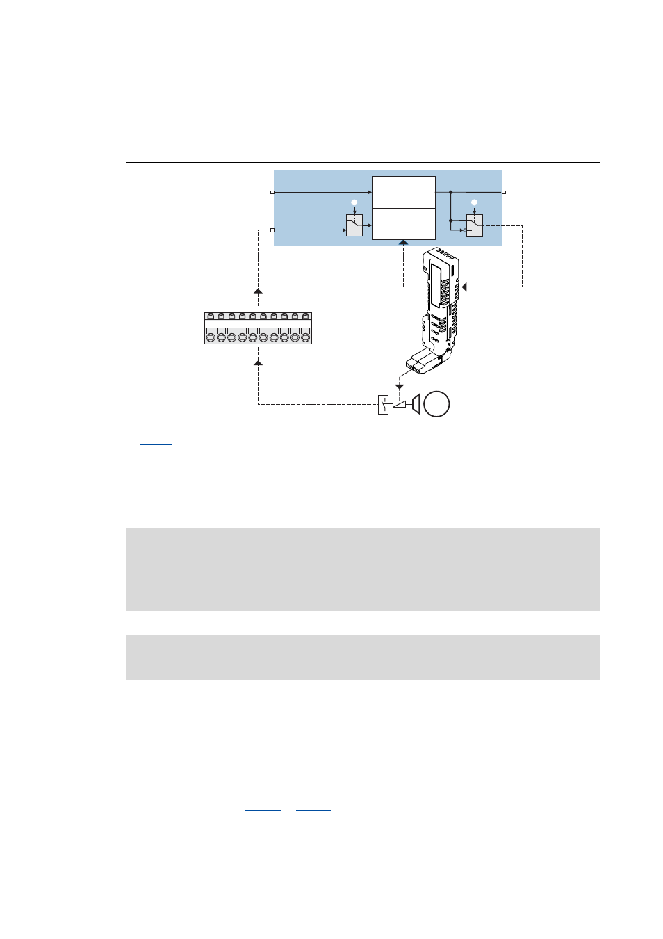
[12-31] Signal configuration of the control and status signal with the motor brake control module E84AZHX0051
Status monitoring by "Motor brake control module status"
(See signal path in fig.
)
• Indirect status detection of the brake function.
• Monitoring of the motor brake control module and the electrical brake circuit.
Status monitoring by "Brake function test"
(See signal path in fig.
or
• Direct function test of the complete brake circuit by microswitches at the brake.
• Wear control of the brake rotor.
: Status input monitoring
: Brake control polarity (for motor brake control module)
Feedback by "Brake function test"
Energising the brake via motor brake control module (E94AZHX0051)
Feedback by "Motor brake control module status"
1
0
M
GI
RFR
DI1
DI2
DI3
DI4
DI5
DI6
DI7
DI8
?
bBrakeApplied
bReleaseBrake
bReleaseBrakeOut
5
1
2
Digital I/O
Brake logic
Monitoring
X107/BDx
E94AZHX0051
1
0
Note!
If an electrically holding (self-releasing) motor holding brake is to be controlled instead
of an electrically releasing (self-holding) motor holding brake, the corresponding control
and status signals must be inverted!
Please observe the notes in the hardware manual for mounting and electrical
installation of the motor holding brake!