5 digital outputs, 1 terminal assignment/electrical data, 2 parameter setting – Lenze E94AxPExxxx User Manual
Page 323: Digital outputs, Terminal assignment/electrical data, Parameter setting, Digital outputs ( 323), 9i/o terminals
Lenze · 9400 Servo PLC· Reference manual · DMS 4.0 EN · 11/2013 · TD05/06
323
9
I/O terminals
9.5
Digital outputs
_ _ _ _ _ _ _ _ _ _ _ _ _ _ _ _ _ _ _ _ _ _ _ _ _ _ _ _ _ _ _ _ _ _ _ _ _ _ _ _ _ _ _ _ _ _ _ _ _ _ _ _ _ _ _ _ _ _ _ _ _ _ _ _
9.5
Digital outputs
The controller is provided with four freely configurable digital outputs.
9.5.1
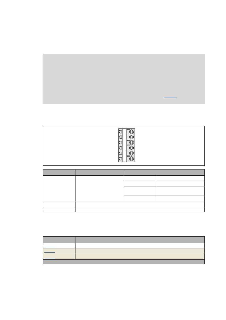
Terminal assignment/electrical data
9.5.2
Parameter setting
Short overview of parameters for the digital outputs:
Note!
Initialisation behaviour:
• After mains switching until the application is started, the digital outputs remain on
FALSE.
Exception handling:
• In the case of a critical exception within the application (e. g. reset), the digital outputs
are set to FALSE, taking the terminal polarity parameterised in
consideration.
Terminal
Application
Electrical data
X4/DO1
...
X4/DO4
Digital output 1 ... 4
LOW level: 0 ... +5 V
HIGH level: +15 ... +30 V
Output current: max. 50 mA per output (external
resistance > 480 Ω at 24 V)
Conversion rate: 1 kHz
X4/24O
External 24 V voltage supply for the digital outputs
X4/GO
Reference potential (digital ground)
GO
24O
DO1
DO2
DO3
DO4
X4
Parameter
Info
Digital output x - terminal pol.
Status: Digital outputs
Status word: Digital outputs
Highlighted in grey = display parameter