5drive interface – Lenze E94AxPExxxx User Manual
Page 147
Lenze · 9400 Servo PLC· Reference manual · DMS 4.0 EN · 11/2013 · TD05/06
147
5
Drive interface
5.3
Device states
_ _ _ _ _ _ _ _ _ _ _ _ _ _ _ _ _ _ _ _ _ _ _ _ _ _ _ _ _ _ _ _ _ _ _ _ _ _ _ _ _ _ _ _ _ _ _ _ _ _ _ _ _ _ _ _ _ _ _ _ _ _ _ _
Display parameters for diagnostic purposes
• In
the current device state is shown.
• In
(status word 1) the current device state is shown in a bit coded manner via
bits 8 ... 11:
•
displays the active function state.
LED status displays
The control of the two LEDs "DRIVE READY" and "DRIVE ERROR" in the middle of the controller's front
panel depends on the device state.
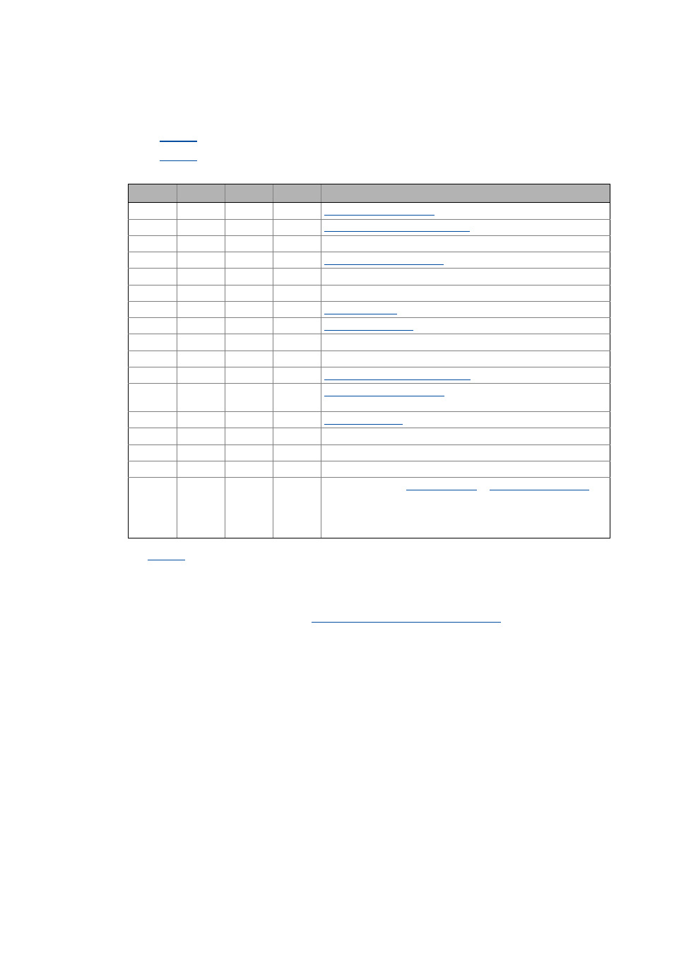
LED status displays for the device state
Bit 11
Bit 10
Bit 9
Bit 8
Meaning
0
0
0
0
0
0
0
1
"Device is ready to switch on" state
0
0
1
0
-
0
0
1
1
0
1
0
0
-
0
1
0
1
-
0
1
1
0
0
1
1
1
1
0
0
0
-
1
0
0
1
-
1
0
1
0
"Quick stop by trouble active" state
1
0
1
1
"Safe torque off active" state
Observe LED on the safety module!
1
1
0
0
1
1
0
1
-
1
1
1
0
-
1
1
1
1
-
x
x
x
x
Displayed message
The displayed message can occur at the same time as the device
states "Device is ready to switch on", "Device is switched on" and
"Operation", if a monitoring component responds for which the error
response "Warning" has been parameterised.