3 drive diagnostics via keypad/bus system, 14 diagnostics & fault analysis – Lenze E94AxPExxxx User Manual
Page 633
Lenze · 9400 Servo PLC· Reference manual · DMS 4.0 EN · 11/2013 · TD05/06
633
14
Diagnostics & fault analysis
14.3
Drive diagnostics via keypad/bus system
_ _ _ _ _ _ _ _ _ _ _ _ _ _ _ _ _ _ _ _ _ _ _ _ _ _ _ _ _ _ _ _ _ _ _ _ _ _ _ _ _ _ _ _ _ _ _ _ _ _ _ _ _ _ _ _ _ _ _ _ _ _ _ _
14.3
Drive diagnostics via keypad/bus system
Keypad display of the controller status
Display parameters
The parameters listed in the following tables serve to query current states and actual values of the
controller for diagnostic purposes, e.g. by using the keypad, a bus system or the »Engineer« (with an
online connection to the controller).
• These parameters are listed in the »Engineer« parameter list and the keypad in the Diagnostics
category.
• A detailed description of these parameters can be found in the chapter "
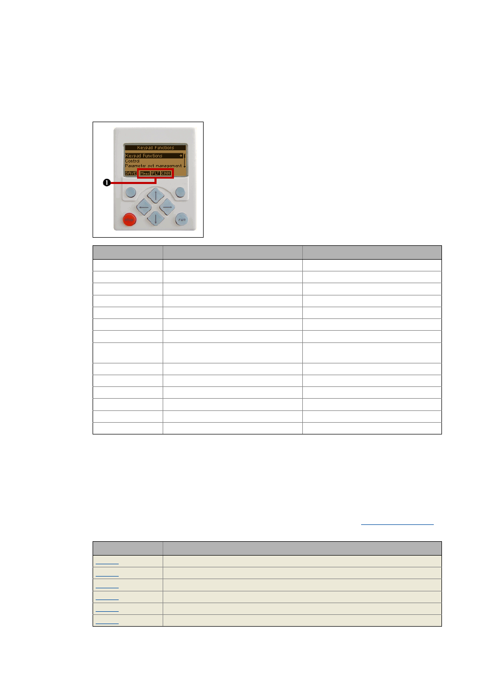
• If the keypad on the front of the controller is connected to the
diagnostic interface X6, the status of the controller is shown
via different icons on the LCD display in the area .
Icon
Meaning
Notes
Controller is ready for operation.
Controller is enabled.
Application in the controller is stopped.
Quick stop active
Controller is inhibited.
The power outputs are inhibited.
Controller is ready to start.
Speed controller 1 at the limit.
The drive is torque-controlled.
Set current limit has been exceeded in motor
or generator mode.
Pulse inhibit active
The power outputs are inhibited.
System fault active
Fault active
Trouble is active
Quick stop by trouble active
Warning is active
Parameter
Display
Device status
Error description
Error number
Actual speed [rpm]
Motor voltage
Motor current