9 monitoring, 1 signal flow, Monitoring – Lenze E94AxPExxxx User Manual
Page 262: Signal flow, 6motor interface, 9 monitoring 6.9.1 signal flow
6
Motor interface
6.9
Monitoring
262
Lenze · 9400 Servo PLC· Reference manual · DMS 4.0 EN · 11/2013 · TD05/06
_ _ _ _ _ _ _ _ _ _ _ _ _ _ _ _ _ _ _ _ _ _ _ _ _ _ _ _ _ _ _ _ _ _ _ _ _ _ _ _ _ _ _ _ _ _ _ _ _ _ _ _ _ _ _ _ _ _ _ _ _ _ _ _
6.9
Monitoring
6.9.1
Signal flow
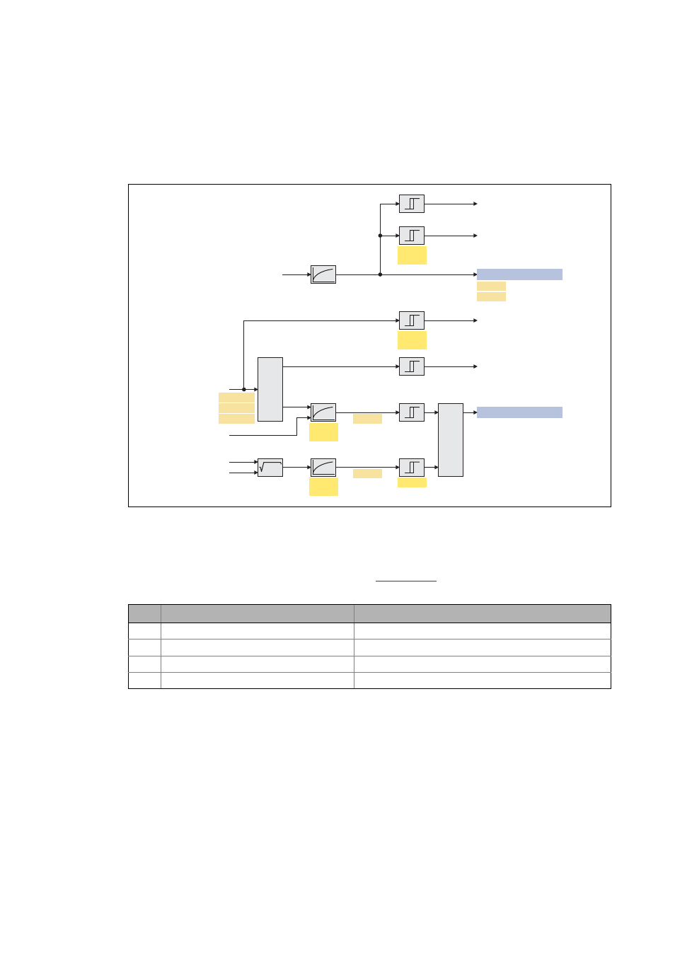
[6-33] Signal flow of motor interface (monitoring)
Internal variables of the motor control (oscilloscope signals)
• The red numbers in brackets listed in the signal flow stand for internal variables of the motor
control, which you can record by means of the
for purposes of diagnostics and
documentation.
a +b
2
2
S
DI_bOVDetected
DI_bUVDetected
MCTRL_dnIxtLoad
const.
const.
const.
MCTRL_dnI2xtLoad
C00597
C00599
C00173
C00174
C00128
C00129
C00786
C00120
C00790
MCTRL_dnDCBusVoltage
C00779
MI_bMotorOverloadWarning
C00053
³1
MI_dnActualDCBusVoltage
(15)
C00055/1
C00055/2
C00055/3
U
V
W
(16)
(17)
(18)
C00018
C00022
const.
Error message
"Failure of motor phase"
Error message "Earth fault detected"
DC-bus voltage
DC-bus voltage filter
Phase currents
Thermal motor model
DC-bus voltage
Actual Q-current
Actual D-current
Error message "Overcurrent detected"
Rotating field frequency
No. Variable of the motor control
Meaning
(15) Voltage.dnActualDCBusVoltage
Actual DC-bus voltage
(16) Current.dnActualCurrentPhaseU
Actual motor current (phase U)
(17) Current.dnActualCurrentPhaseV
Actual motor current (phase V)
(18) Current.dnActualCurrentPhaseW
Actual motor current (phase W)