5 brake time response, 12 basic drive functions, Danger – Lenze E94AxPExxxx User Manual
Page 561
Lenze · 9400 Servo PLC· Reference manual · DMS 4.0 EN · 11/2013 · TD05/06
561
12
Basic drive functions
12.12
Brake control
_ _ _ _ _ _ _ _ _ _ _ _ _ _ _ _ _ _ _ _ _ _ _ _ _ _ _ _ _ _ _ _ _ _ _ _ _ _ _ _ _ _ _ _ _ _ _ _ _ _ _ _ _ _ _ _ _ _ _ _ _ _ _ _
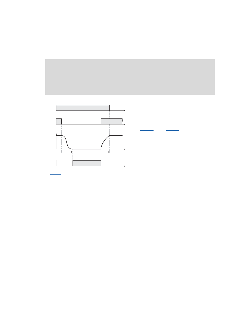
12.12.2.5 Brake time response
Application and release time
[12-35] Definition of the application and release time with the example of the PM brake
Tip!
The application and release times do not only vary between the brake types but also
depend on the basic conditions in the plant:
• Parameters of the hardware (cable length, temperature, level of supply voltage etc.)
• Contact elements used (motor brake control module or contactor at the digital output)
• Type of overvoltage limitation/suppressor circuit
For optimisation purposes, detect in individual cases the response times by measurement.
Danger!
A wrong setting of the closing and opening time can cause a wrong activation of the
motor holding brake!
• When the closing time is set too low, the controller is inhibited and the drive gets
torqueless before the motor holding brake is closed completely.
: Brake closing time
: Brake opening time
CINH = controller inhibit
• Every mechanical motor holding brake has
a construction-conditioned application
and opening time which has to be taken
into consideration by the brake control and
which for this purpose has to be set in
and in
• The information on the application and
opening time of a Lenze-motor holding
brake can be found in the corresponding
Operating Instructions in the chapter
"Technical data".
• If the application and release times are too
long, this is uncritical in respect of safety
but leads to unnecessarily long delays
during cyclical braking processes.
t
t
t
CINH
t
Stopping/Standstill
BRK_bReleaseBrakeOut
I
BRK