2 ixt utilisation - brake transistor, Ixt utilisation - brake transistor, 8braking operation – Lenze E94AxPExxxx User Manual
Page 312
8
Braking operation
8.2
Monitoring
312
Lenze · 9400 Servo PLC· Reference manual · DMS 4.0 EN · 11/2013 · TD05/06
_ _ _ _ _ _ _ _ _ _ _ _ _ _ _ _ _ _ _ _ _ _ _ _ _ _ _ _ _ _ _ _ _ _ _ _ _ _ _ _ _ _ _ _ _ _ _ _ _ _ _ _ _ _ _ _ _ _ _ _ _ _ _ _
8.2.2
Ixt utilisation - brake transistor
The controller is provided with a monitoring function for the Ixt utilisation of the internal brake
transistor.
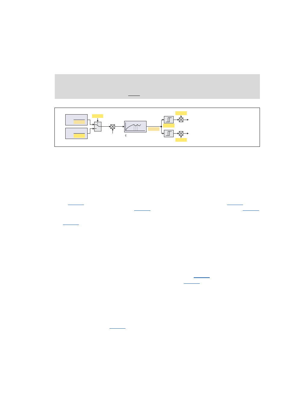
[8-1]
Signal flow of Ixt utilisation - brake chopper
• Monitoring is based on a mathematical model which calculates the braking current from the
current DC-bus voltage and the brake resistance parameterised.
• Hence, monitoring can be activated although no brake resistor is connected and can
therefore also be used for a testing mode to check the parameterisation.
• During the calculation the thermal utilisation of the brake transistor is taken into consideration
by the use of an accordingly adapted time constant.
• In
it can be selected whether the minimum brake resistance (display in
) which
depends on the network setting in
) or the brake resistor value parameterised in
is to be used as a reference for calculating the utilisation.
•
displays the calculated utilisation of the brake transistor in [%].
• A 100 % utilisation corresponds to the continuous braking power which is provided by the
integrated brake chopper at a DC-bus voltage of 790 V (or 390 V at a mains voltage of 230 V).
• The maximum braking power (assuming that the utilisation starts at 0 %) can be provided for
a time period depending on the device.
• The calculated utilisation is provided as oscilloscope signal Common.dnIxtBrakeChopper to
check the braking operation while the system is running
(scaling: 2
30
≡ 100 %).
• If the utilisation exceeds the advance warning threshold set in
, "Brake chopper: Ixt >
C00570" is entered in the logbook and the response set in
is activated.
• When the utilisation reaches the limit value (100 %):
• The activation of the brake chopper is reset to the permanently permissible mark-to space
ratio (taking the parameterised brake resistance into consideration). (The brake chopper is
activated with 4 kHz, which means that it can be switched on/off at minimum intervals of
250 μs.)
• The response set in
(default setting: "No response") is activated with the
corresponding effects on the state machine and the inverter.
Note!
The braking operation will never be switched off by this monitoring function.
Ixt
C00137
1
0
C00134
C00129
C00133
T
= 0
Off
T
= 1
On
100 %
C00570
C00569
C00573
Logbook entry "Brake chopper: Ixt > C00570"
Logbook entry "
"
Brake transistor: Ixt overload
U
DC_act
U
DC_act
I
=
Br
I
=
Br
I
Br
= f(duty cycle, R )
Br