1 modes of operation, 2 signal configuration, Signal configuration ( 555) – Lenze E94AxPExxxx User Manual
Page 555: 12 basic drive functions
Lenze · 9400 Servo PLC· Reference manual · DMS 4.0 EN · 11/2013 · TD05/06
555
12
Basic drive functions
12.12
Brake control
_ _ _ _ _ _ _ _ _ _ _ _ _ _ _ _ _ _ _ _ _ _ _ _ _ _ _ _ _ _ _ _ _ _ _ _ _ _ _ _ _ _ _ _ _ _ _ _ _ _ _ _ _ _ _ _ _ _ _ _ _ _ _ _
12.12.2.1 Modes of operation
Various operating modes are available in
for different applications and tasks:
•
Mode 0: Brake control is switched off
•
Mode 1/11: Direct control of the brake
• Without a specific logic or automatic system, can for instance be used to carry out a simple
check on whether the brake switches correctly.
•
Mode 2/12: Automatic control of the brake
• The normal mode for the control of mech. holding brakes with and without holding torque
precontrol.
•
Mode 22: Automatic DC-injection braking
• DC-injection braking for V/f control and sensorless vector control.
12.12.2.2 Signal configuration
The signal configuration of the control and status signals for the brake logic and monitoring
function is executed via the parameters shown in the following signal flows.
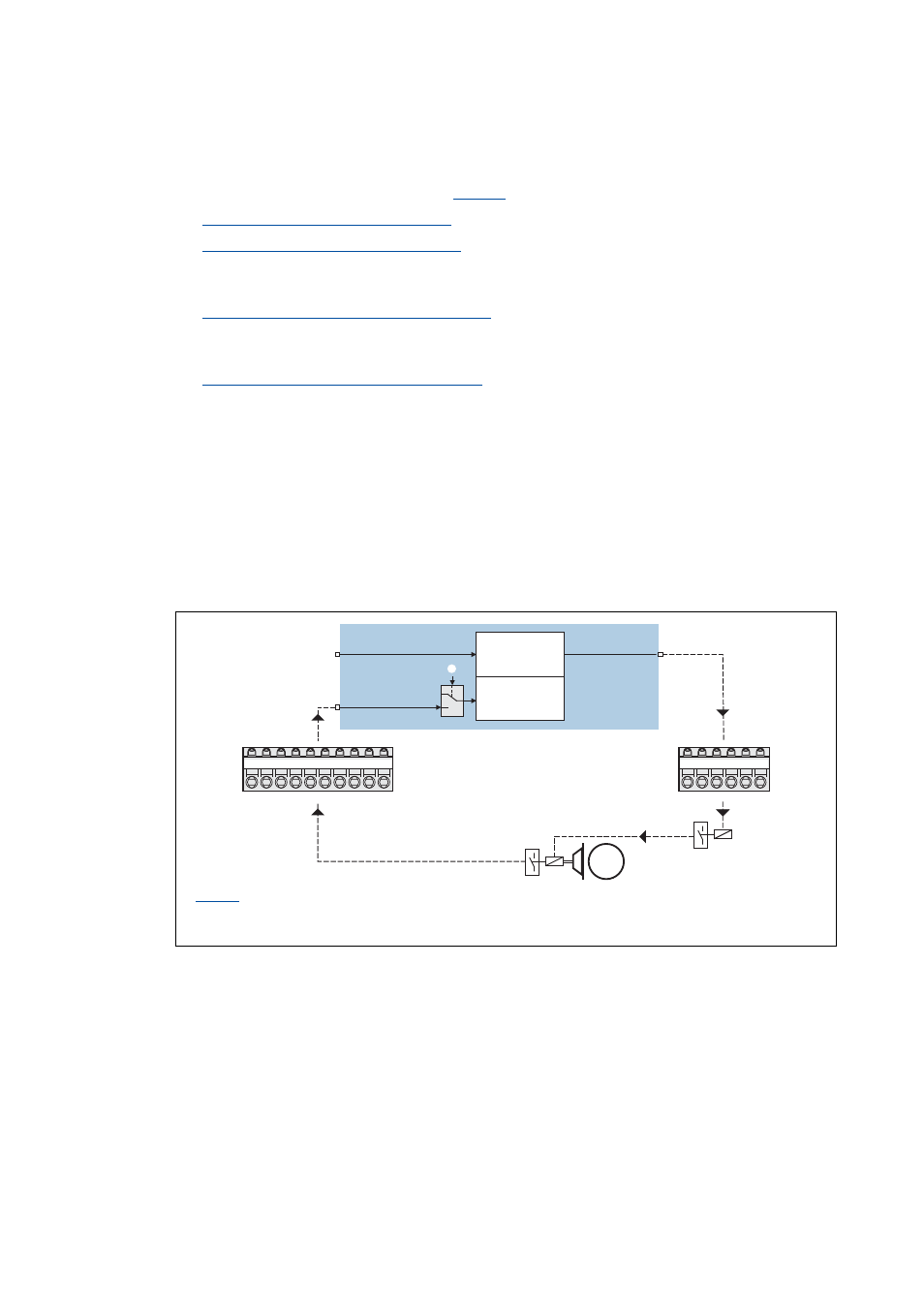
Direct brake control
This triggering of the holding brake does not need the motor brake control module:
[12-29] Direct control of the motor holding brake
: Status input monitoring
Brake control via relay/contactor at digital output
Feedback by "Brake function test"
1
0
M
GI
RFR
DI1
DI2
DI3
DI4
DI5
DI6
DI7
DI8
GO
24O
DO1
DO2
DO3
DO4
?
bBrakeApplied
bReleaseBrake
bReleaseBrakeOut
1
0
Digital I/O
Digital I/O
Brake logic
Monitoring