6motor interface, 8 parameterisable additional functions – Lenze E94AxPExxxx User Manual
Page 251
Lenze · 9400 Servo PLC· Reference manual · DMS 4.0 EN · 11/2013 · TD05/06
251
6
Motor interface
6.8
Parameterisable additional functions
_ _ _ _ _ _ _ _ _ _ _ _ _ _ _ _ _ _ _ _ _ _ _ _ _ _ _ _ _ _ _ _ _ _ _ _ _ _ _ _ _ _ _ _ _ _ _ _ _ _ _ _ _ _ _ _ _ _ _ _ _ _ _ _
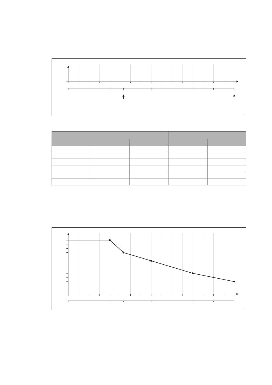
• For this example currents were selected that are part of the interpolation points 5, 9, 13, and
15, and a measurement at rated motor current was carried out:
[6-24] Saturation characteristic: Distribution of the grid points
4. Create a characteristic based on the values calculated for Vp.
• Here, the values of the grid points which have not been adjusted must be determined by
interpolation between two values.
• Note: In this example it was assumed that the inductance does not change considerably
below 3.75 A. For this reason the same Vp value resulting from a measurement with a motor
current of 3.75 A was used for all interpolation points below 3.75 A.
[6-25] Determined saturation characteristic
Rated motor current
Maximum process current (≡ 100 %)
15 A
2
3
4
5
6
7
8
9
10
11
12
13
14
15
16
17
7.5 A
3.75 A
11.25 A
12.38 A
5 A
0
6.25
12.5
18.75
25
31.25
37.5
43.75
50
56.25
62.5
68.75
75
81.25
87.5
93.75
100
0 A
I
max
[%]
Vp
Tn
[V/A]
[ms]
1
Specifications for adjustment
Measured values
Grid point
Scaling
Setting in C00022
Vp [V/A]
Tn [ms]
5
0.25 * 15 A =
3.75 A
13
6.5
9
0.5 * 15 A =
7.5 A
8
4
13
0.75 * 15 A =
11.25 A
5
2.5
15
0.875 * 15 A =
12.38 A
4
2
17
1.0 * 15 A =
15 A
3
1.7
Rated motor current =
5 A
10
5
15 A
2
3
4
5
6
7
8
9
10
11
12
13
14
15
16
17
7.5 A
3.75 A
11.25 A
12.38 A
5 A
0
6.25
12.5
18.75
25
31.25
37.5
43.75
50
56.25
62.5
68.75
75
81.25
87.5
93.75
100
Vp [V/A]
0 A
0
1
2
3
4
5
6
7
8
9
10
11
12
13
1
I
max
[%]