2 i/o status information, 3 control information, I/o status information ( 410) – Lenze E94AxPExxxx User Manual
Page 410: Control information ( 410), 11 safety engineering
11
Safety engineering
11.3
System block "LS_SafetyModuleInterface"
410
Lenze · 9400 Servo PLC· Reference manual · DMS 4.0 EN · 11/2013 · TD05/06
_ _ _ _ _ _ _ _ _ _ _ _ _ _ _ _ _ _ _ _ _ _ _ _ _ _ _ _ _ _ _ _ _ _ _ _ _ _ _ _ _ _ _ _ _ _ _ _ _ _ _ _ _ _ _ _ _ _ _ _ _ _ _ _
11.3.2
I/O status information
Via the bit coded status signal SMI_dnIoState of the LS_SafetyModuleInterface SB, the SM3xx
safety module transmits the status of the safe inputs and outputs to the application.
• Which bits are supported depends on the safety module used.
Tip!
For decoding the status signal into individual boolean status signals, simply connect the
output SMI_dnIoState to the L_DevSMStateDecoderIO FB which is available in the function
library from V2.0.
11.3.3
Control information
Via the bit coded control signal SMI_dwControl of the LS_SafetyModuleInterface SB, the SM3xx
safety module transmits information on safety functions requested, or on active safety functions to
the application.
• Several safety functions can be requested/active at the same time.
• Which bits are supported depends on the safety module used.
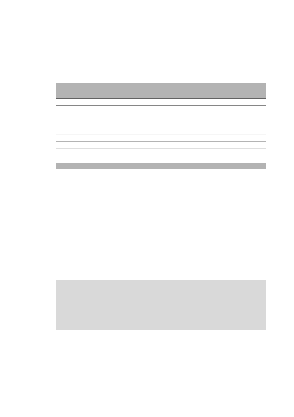
Bit coding of the SMI_dnIoState status signal
Bit
Name
Meaning
0
SD-In1
Sensor input 1 in ON state.
1
SD-In2
Sensor input 2 in ON state.
2
SD-In3
Sensor input 3 in the ON state.
3
SD-In4
Sensor input 4 in the ON state.
5
AIS
Restart acknowledgement via terminal effected (negative edge: 10).
6
AIE
Error acknowledgement via terminal effected (negative edge: 10).
8
PS_AIS
Restart acknowledgement via safety bus effected (positive edge: 01)
9
PS_AIE
Error acknowledgement via safety bus effected (positive edge: 01)
12
SD-Out1
Safe output 1 (feedback output) in the ON state.
Bits not listed are reserved for future extensions!
Note!
The corresponding actions (e.g. braking, braking to standstill, holding of the standstill
position) must be executed by the application, e.g. via the basic function "
• To integrate the basic function "Limiter", the output SMI_dwControl is to be
connected to the input LIM_dwControl of the LS_Limiter system block.