2 effect of c01130 on the sync phase position, Effect of c01130 on the sync phase position, 10 "can on board" system bus – Lenze E94AxPExxxx User Manual
Page 353
Lenze · 9400 Servo PLC· Reference manual · DMS 4.0 EN · 11/2013 · TD05/06
353
10
"CAN on board" system bus
10.6
Process data transfer
_ _ _ _ _ _ _ _ _ _ _ _ _ _ _ _ _ _ _ _ _ _ _ _ _ _ _ _ _ _ _ _ _ _ _ _ _ _ _ _ _ _ _ _ _ _ _ _ _ _ _ _ _ _ _ _ _ _ _ _ _ _ _ _
Sync application cycle
This parameter influences the effect of the sync phase position (
) with regard to the instant
of acceptance of the synchronous PDOs by the application or the instant of transmission of the
synchronous PDOs to the system bus.
• The sync application cycle can be set in
. The set value is automatically rounded down to
full 1000 μs.
• The resulting PDO delay can be calculated with the following formula taking into consideration
an internal processing time of 150 s: PDO delay= (sync cycle time - sync phase position + 150 μs)
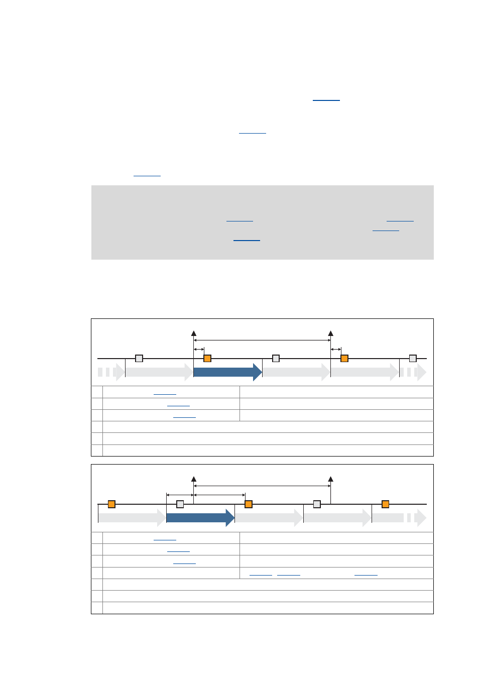
10.6.5.2
Effect of C01130 on the sync phase position
Note!
If the sync application cycle in
is set higher than the sync cycle time (
the behaviour is undefined. The same applies if the sync phase position (
) is set
higher than the sync cycle time (
).
Usually, no synchronous PDOs are then applied to the system bus anymore.
Example 1:
Sync cycle time (
)
= 2000 μs
Sync phase position (
)
= 0 μs
Sync application cycle (
)
= 1000 μs
Instant of acceptance/transmission of synchronous PDOs
Inactive instant of acceptance
n Device cycle
Example 2:
Sync cycle time (
)
= 2000 μs
Sync phase position (
)
= 400 μs
Sync application cycle (
)
= 1000 μs
PDO delay
= (
= 750 μs
Instant of acceptance/transmission of synchronous PDOs
Inactive instant of acceptance
n Device cycle
0
1
0
1
150 µs
n-1
1
150 µs
n
n+1
n+2
SYNC
SYNC
0
1
0
1
n+3
n-1
n
0
n+1
n+2
SYNC
SYNC