2 possible settings by dip switch, 1 setting the node address, 10 "can on board" system bus – Lenze E94AxPExxxx User Manual
Page 336
10
"CAN on board" system bus
10.2
Possible settings by DIP switch
336
Lenze · 9400 Servo PLC· Reference manual · DMS 4.0 EN · 11/2013 · TD05/06
_ _ _ _ _ _ _ _ _ _ _ _ _ _ _ _ _ _ _ _ _ _ _ _ _ _ _ _ _ _ _ _ _ _ _ _ _ _ _ _ _ _ _ _ _ _ _ _ _ _ _ _ _ _ _ _ _ _ _ _ _ _ _ _
10.2
Possible settings by DIP switch
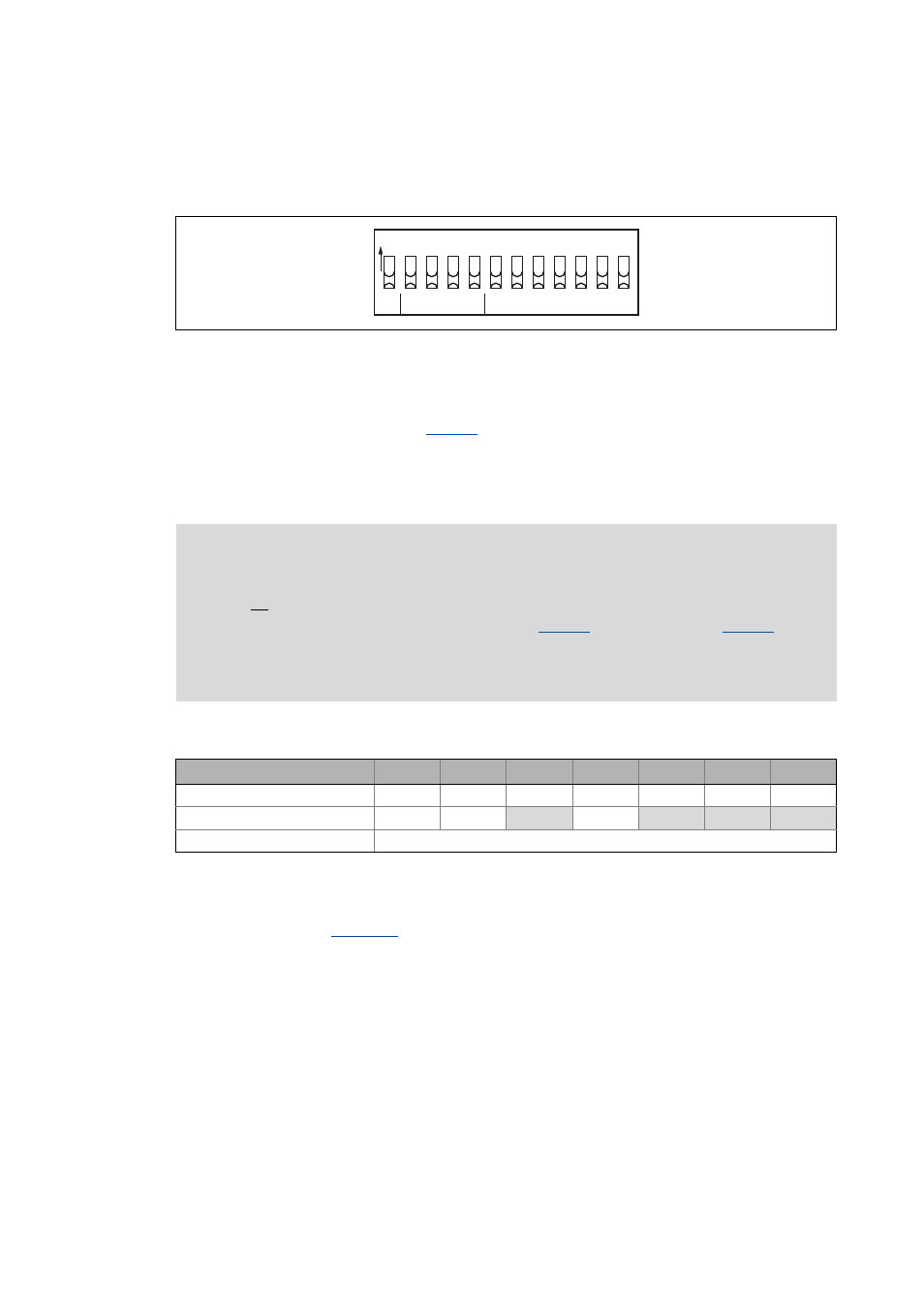
The DIP switches on the front of the memory serve to set the baud rate and the node address.
[10-1] DIP switch
10.2.1
Setting the node address
The node address can be set via code
or with the DIP switches 1 to 64.
• The labelling on the housing corresponds to the values of the individual DIP switches for
determining the node address.
• Valid address range: 1 … 127
Example: Setting of the node address 23
Tip!
The node address resulting from the setting of the DIP switches at the last mains switching
is displayed in
Baud
CAN Address
O
N
c
d
b
a
64
32
16
8
4
2
1
Note!
• The addresses of the nodes must differ from each other.
• All twelve DIP switches = OFF (Lenze setting):
• At switching on, the settings under code
(node address) and
(baud
rate) will become active.
• Switch the voltage supply of the basic device off and then on again to activate altered
settings.
DIP switch
64
32
16
8
4
2
1
Switch position
OFF
OFF
ON
OFF
ON
ON
ON
Value
0
0
16
0
4
2
1
Node address
= Sum of the values = 16 + 4 + 2 + 1 = 23