1 setting the error response, 14 diagnostics & fault analysis – Lenze E94AxPExxxx User Manual
Page 640
14
Diagnostics & fault analysis
14.5
Monitoring
640
Lenze · 9400 Servo PLC· Reference manual · DMS 4.0 EN · 11/2013 · TD05/06
_ _ _ _ _ _ _ _ _ _ _ _ _ _ _ _ _ _ _ _ _ _ _ _ _ _ _ _ _ _ _ _ _ _ _ _ _ _ _ _ _ _ _ _ _ _ _ _ _ _ _ _ _ _ _ _ _ _ _ _ _ _ _ _
14.5.1
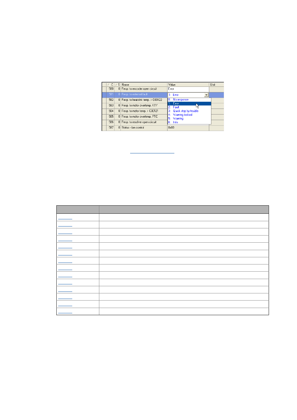
Setting the error response
If a monitoring function responds, the response set for this monitoring function (quick stop by
trouble, warning, fault, etc.) is triggered.
• For many monitoring functions the response can be individually parameterised via parameters.
Tip!
The table in the chapter "
" contains the error messages for which the
response can be set.
Warning thresholds
Some of the monitoring functions are activated if a defined warning threshold (e.g. temperature)
has been exceeded.
• The corresponding preset threshold values can be changed via the following parameters:
Parameter
Info
Motor overload protection (I²xt)
Motor temp. warning threshold
Heatsink temp. warn. threshold
Device utilisation warning threshold
CPU temp. warning threshold
Mot. overload warning threshold
Thermal time constant of motor
Undervoltage (LU) threshold
Warning thres. brake transistor
Warning thres. brake resistor
Speed monitoring tolerance
Threshold max. speed reached
Motor phase failure threshold
Max. motor current threshold