6motor interface – Lenze E94AxPExxxx User Manual
Page 264
6
Motor interface
6.9
Monitoring
264
Lenze · 9400 Servo PLC· Reference manual · DMS 4.0 EN · 11/2013 · TD05/06
_ _ _ _ _ _ _ _ _ _ _ _ _ _ _ _ _ _ _ _ _ _ _ _ _ _ _ _ _ _ _ _ _ _ _ _ _ _ _ _ _ _ _ _ _ _ _ _ _ _ _ _ _ _ _ _ _ _ _ _ _ _ _ _
Structure of the I
2
xt monitoring
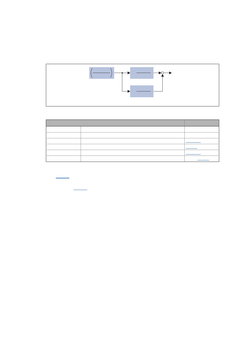
The introduction of a two-component model with two time constants (one for the winding and the
other for the housing/laminated core) serves to display the thermal behaviour of the motor up to
500% of the rated current:
[6-34] Structure of the motor monitoring
Calculation with only one time constant
With
= "0 %" the time constant for the winding is not considered and the thermal model is
only calculated with the time constant set for the housing/laminated core.
• The setting
= "0 %" is reasonable if for example the two time constants are not known.
• The calculation simplified due to this setting corresponds to the calculation in the previous
Lenze devices (e.g. 9300 servo inverter or ECS).
Thermal utilisation of the motor in [%]
k
1
1
(1 + p
)
t
1
k
2
1
(1 + p
)
t
2
I
act motor
I
perm motor
(n)
2
Parameter
Setting
I
act motor
Actual motor current
-
I
perm motor
(n)
Permissible motor current (speed-dependent)
-
τ
1
Therm. time constant coil
k
1
Percentage of the winding in the final temperature
τ
2
Therm. time constant plates
k
2
Percentage of the steel plates in the final temperature