4 implementing system blocks in »plc designer, Implementing system blocks in »plc designer, 4plc functionality – Lenze E94AxPExxxx User Manual
Page 56: Inputs outputs
4
PLC functionality
4.5
Use of system blocks
56
Lenze · 9400 Servo PLC· Reference manual · DMS 4.0 EN · 11/2013 · TD05/06
_ _ _ _ _ _ _ _ _ _ _ _ _ _ _ _ _ _ _ _ _ _ _ _ _ _ _ _ _ _ _ _ _ _ _ _ _ _ _ _ _ _ _ _ _ _ _ _ _ _ _ _ _ _ _ _ _ _ _ _ _ _ _ _
Example: System block DIGITAL_IO of the »9400 ServoPLC«
If you want to use the digital input 1 and the digital output 1 of the »9400 ServoPLC«, carry out the
following steps:
1. Implement the DIGITAL_IO system block into the control configuration of the »PLC Designer«.
Implementing system blocks in »PLC Designer«
2. For access to the digital input 1:
• The digital inputs can be found under Inputs_Digital[SLOT]
• Assign the system variable DIGIN_bIn1 to a POU input.
3. For access to the digital output 1:
• The digital outputs can be found under Outputs_Digital[SLOT]
• Assign the system variable DIGOUT_bOut1 to a POU output.
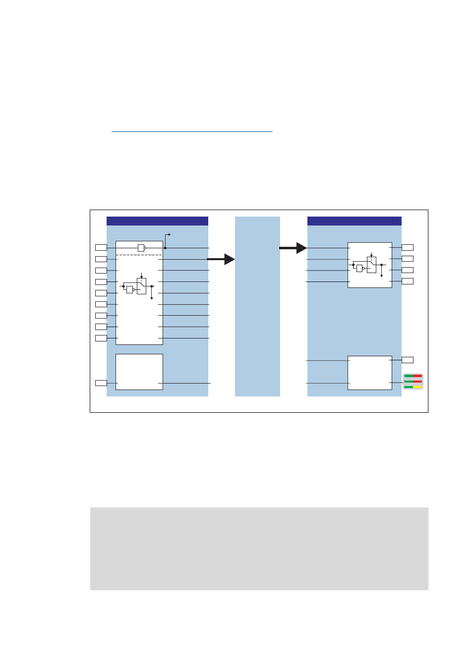
[4-2]
Connecting the system block DIGITAL_IO of the »9400 ServoPLC« with a POU
4.5.4
Implementing system blocks in »PLC Designer«
The system blocks are the interface between PLC program and the peripherals of the controller (e.g.
digital inputs and outputs).
In order to access from the PLC program to the system blocks, the system blocks must be inserted
into the control configuration.
LS_DigitalInput
POU
DIGIN_bIn1
DIGIN_bIn2
DIGIN_bIn5
DIGIN_bIn4
DIGIN_bIn3
X5
X4
DIGIN_bIn6
DIGIN_bIn7
DIGIN_bIn8
DIGIN_bCInh
DIGIN_
bStateBusIn
1
0
1
C00114/1...8
C00443/1...8
CONTROL
RFR
A1
DI1
A2
DI2
A3
DI3
A4
DI4
DI5
DI6
DI7
DI8
SB
SB
X2
X2
LS_DigitalOutput
DIGOUT_bOut1
DIGOUT_
bStateBusOut
DIGOUT_bOut3
DIGOUT_bOut2
1
0
1
C00118/1...4
DIGOUT_bOut4
DIGOUT_
bUserLED
User
LED
C00444/1...4
CONTROL
DriveInterface
1
Inputs
Outputs
Note!
The process image of the system blocks is created by the »9400 ServoPLC« in the task
with the highest priority, irrespective of the interval time set for this task.
In the PLC standard project, the ApplicationTask has the highest priority (priority 1).
Thus, a consistent process image is only available in the ApplicationTask. Therefore, the
system blocks should only be accessed in this task.