6motor interface – Lenze E94AxPExxxx User Manual
Page 194
6
Motor interface
6.4
Servo control (SC)
194
Lenze · 9400 Servo PLC· Reference manual · DMS 4.0 EN · 11/2013 · TD05/06
_ _ _ _ _ _ _ _ _ _ _ _ _ _ _ _ _ _ _ _ _ _ _ _ _ _ _ _ _ _ _ _ _ _ _ _ _ _ _ _ _ _ _ _ _ _ _ _ _ _ _ _ _ _ _ _ _ _ _ _ _ _ _ _
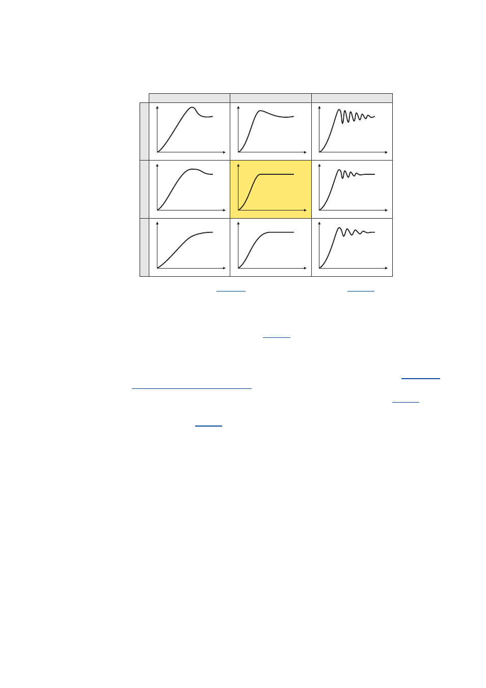
6. Evaluate the step response:
7. Change the gain Vp under
.
8. Repeat steps 4 ... 6 until the optimum step response of the motor current is reached.
• In the optimised state the current rise time typically is 0.5 ... 1 ms.
• If the adjustment results are not satisfactory, the decoupling network can be
additionally activated via the setting
= "1". After this, repeat the steps 2 ... 6.
• In case of MCS, satisfying results may only be achieved with a current-dependent
correction of the current controller parameters based on the saturation behaviour of the
motor stator leakage inductance. For this purpose, it is required to use a motor with an
electronic nameplate (ENP) or to set the saturation characteristic manually.
of the stator leakage inductance...
9. After the optimisation has been completed, deactivate the test mode again (
= "0:
Test mode deactivated").
10. Save parameter set (
= "11: Save start parameters").
I
t
I
t
I
t
I
t
I
t
I
t
I
t
I
t
I
t
Vp < Vp opt.
Vp = Vp opt.
Vp > Vp opt.
Tn
<
T
n
opt.
Tn
=
T
n
opt.
Tn
>
T
n
opt.