Connection of devices via remote interface, 13 connection of devices via remote interface – Metrohm 746 VA Trace Analyzer User Manual
Page 83
3 Installation
746 VA Trace Analyzer / 747 VA Stand
3-56
3.13 Connection of devices via remote interface
The 746 VA Trace Analyzer is fitted with a 25-pin remote interface (connection 23
23
”Control Lines”) with a total of 16 control lines. Any external device can be attached
to the 8 inputs (scan) and 8 outputs (set) and can be scanned or set via these lines.
The current status of the control lines at the 746 VA Trace Analyzer is shown on the
”VA TRACE ANALYZER” page as follows (see section 5.3.1):
Ctrl.lines # 87654321
––––––––––––––––––––––––
Scan 01001111
Set 00011001
The instruction
SCANCTRL
is used to scan the input lines within programs, whereas
the
SETCTRL
instruction (see section 5.7) serves to set the output lines.
The pin assignment of the remote interface, the pin functions and the electrical
conditions and statuses are shown in the Table on page 3-56.
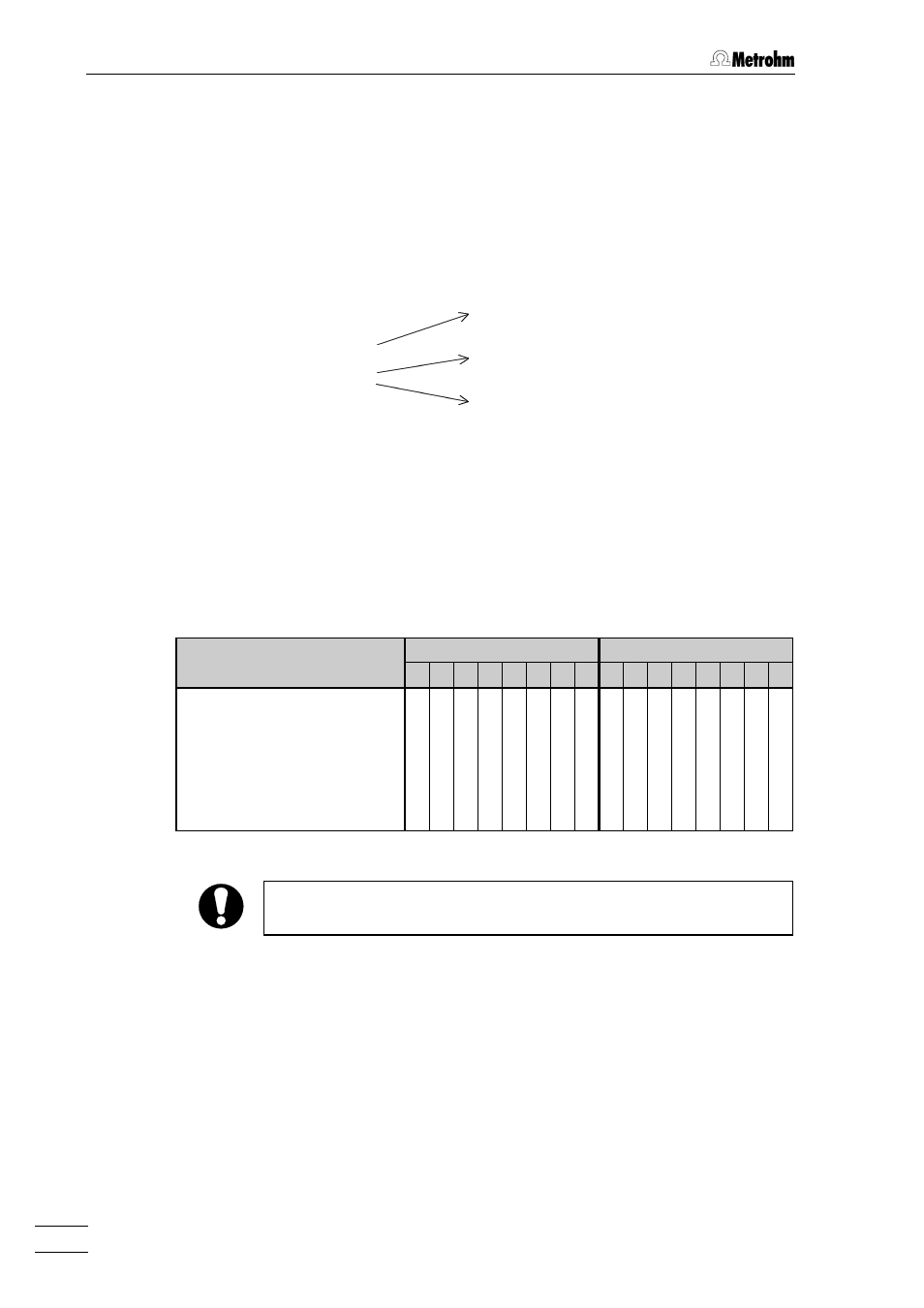
The following Table shows which input and output lines are used for the external
start/stop function, the pipetting handle and the cables for the 708 Sampling Unit
and 683 Pump Units.
Input
Output
1 2 3 4 5 6 7 8 1 2 3 4 5 6 7 8
External start
l
External stop
l
6.1562.040 Pipetting handle
l
l
6.2143.100 Cable (1
×
708)
l l l
6.2143.110 Cable (2
×
708)
l l l l l l
6.2143.120 Cable (1
Ч
708, 4
Ч
683)
l l l l l l l
The output line 8 can be used only for the 6.1562.040 Pipetting
handle.
Numbering of the input and
output control lines (1...8)
Inputs
0 = inactive, off
5 V
1 = active, on
0 V
Outputs
0 = inactive, off
5 V
1 = active, on
open