2 baselines for waves – Metrohm 746 VA Trace Analyzer User Manual
Page 476
6.7 Baseline calculation
746 VA Trace Analyzer / 747 VA Stand
6-13
If overlapping exists, the following 4 cases are distinguished:
– Negligible overlapping:
approx.peak1/approx.peak2 > 10
If the ratio of the estimated peak heights of the two neighbouring peaks
is larger that 10, the influence of the overlapping can be completely ig-
nored.
– Admissible overlapping:
approx.peak1/approx.peak2
≤≤ 10
∆∆U.peak > 0.9
*
(U.width1 + U.width2)
If the difference between the two peak voltages
∆∆U.peak
is greater
than 90% of the sum of the two peak widths (overlapping <10%), this is
shown in the results with the comments
front overlapping
or
rear
overlapping
. The overlapping leads to no noticeable falsification of the
results, an evaluation with
Scope = whole
is still possible.
– Critical overlapping:
approx.peak1/approx.peak2
≤≤ 10
∆∆U.peak ≤≤ 0.9
*
(U.width1 + U.width2)
∆∆U.peak > 0.6
*
(U.width1 + U.width2)
If the difference between the two peak voltages
∆∆U.peak
is 60 ... 90%
of the sum of the two peak widths (overlapping 10...40%), this is shown
in the results with the comments
crit. front ovlp.
or
crit. rear
ovlp.
. The overlapping is so large that an evaluation with
Scope =
whole
leads to relatively large errors. However, an evaluation with
Scope = f.double/r.double
or possibly
Scope = f.half/r.half
is
possible.
– Inadmissible overlapping:
approx.peak1/approx.peak2
≤≤ 10
∆∆U.peak ≤≤ 0.6
*
(U.width1 + U.width2)
If the difference between the two peak voltages
∆∆U.peak
is less than
60% of the sum of the two peak widths (overlapping >40%), this is
shown in the results with the comments
illeg. front ovlp.
or
illeg. rear ovlp.
. The overlapping is so large that an evaluation is no
longer possible. In this case, an attempt must be made to separate the
two peaks by chemical or measurement technique measures (see sec-
tion 7.5.8).
6.7.2
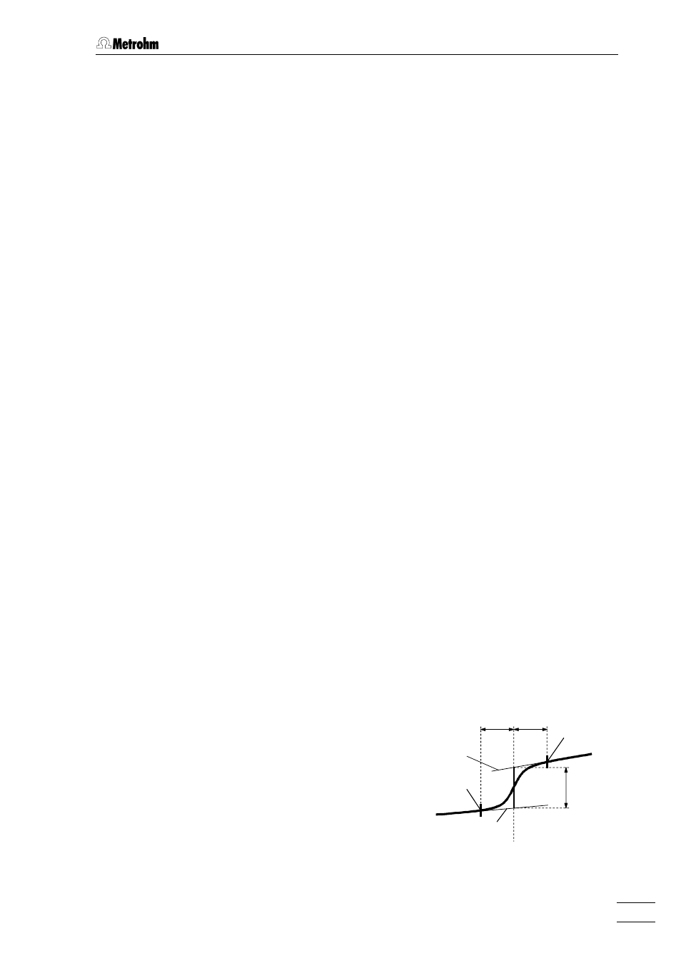
Baselines for waves
With wave-shaped curves which have been recorded with the DCTMODE meas-
urement mode, the two tangents before and after the wave are determined as
baselines. These tangents are then used to calculate the wave current
I.wave
.
The selection possibility for the base-
line parameters is restricted here to
Type
=
linear
and
Scope
=
whole
. The
base points
dU.front
and
dU.rear
and the associated slopes
S.front
and
S.rear
can be determined
automatically or entered manually.
With wave-shaped curves, no display
of the subtracted curve
subtracted
is
possible.
S.front
S.rear
U.wave
I.wave
dU.front dU.rear
Base point
(rear)
Base point
(front)