1 apparent key detection, 1 apparent key detection -3, Figure 26-2. 8 x 8 key array diagram -3 – Cirrus Logic EP93xx User Manual
Page 765: Figure 26-2, Apparent key detection
DS785UM1
26-3
Copyright 2007 Cirrus Logic
Keypad Interface
EP93xx User’s Guide
2
6
2
6
26
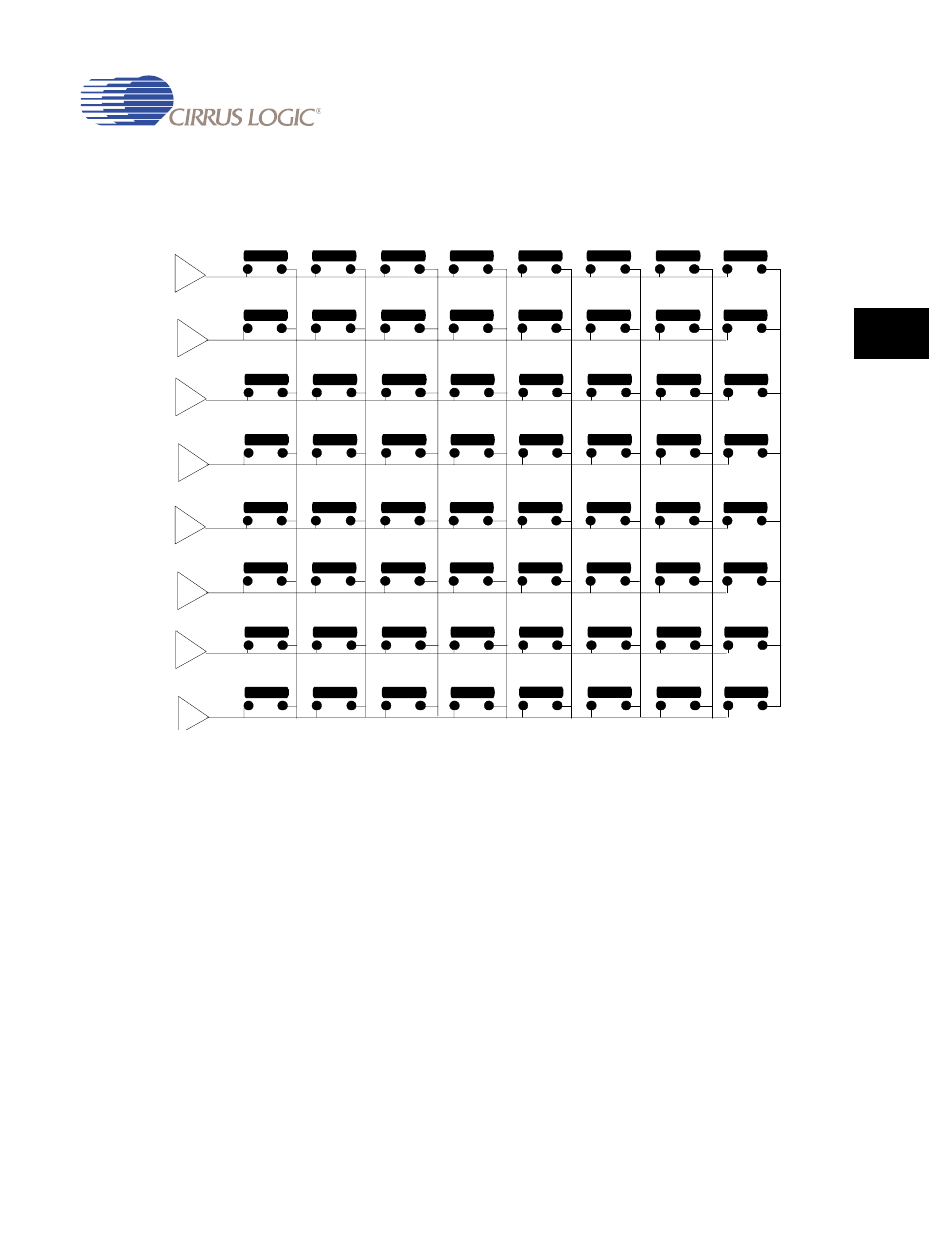
Figure 26-2. 8 x 8 Key Array Diagram
26.2.1 Apparent Key Detection
When more than two keys are pressed, the key array controller may detect “apparent” keys.
An apparent key detection is caused by misinterpreting the basic electrical signals. For
example, in
, three keys are pressed:
•
(ROW0, COL3) with address 0x03
•
(ROW3, COL0) with address 0x18
•
(ROW3, COL3) with address 0x1B
The controller’s instruction is to decode the two keys with the lowest addresses. Therefore
the system interprets the electrical signals as:
•
An apparent key address of 0x00 at (ROW0, COL0)]
•
An actual key address of 0x03 at (ROW0, COL3)
•
No press for address 0x18 at (ROW3, COL0)
ROW 0
KEY 00H
KEY 01H
KEY 02H
KEY 03H
KEY 04H
KEY 05H
KEY 06H
KEY 07H
ROW 1
KEY 08H
KEY 09H
KEY 0AH
KEY 0BH
KEY 0CH
KEY 0DH
KEY 0EH
KEY 1FH
ROW 2
KEY 10H
KEY 11H
KEY 12H
KEY 13H
KEY 14H
KEY 15H
KEY 16H
KEY 17H
ROW 3
KEY 18H
KEY 19H
KEY 1AH
KEY 1BH
KEY 1CH
KEY 1DH
KEY 1EH
KEY 1FH
ROW 4
KEY 20H
KEY 21H
KEY 22H
KEY 23H
KEY 24H
KEY 25H
KEY 26H
KEY 27H
ROW 5
KEY 28H
KEY 29H
KEY 2AH
KEY 2BH
KEY 2CH
KEY 2DH
KEY 2EH
KEY 2FH
ROW 6
KEY 30H
KEY 31H
KEY 32H
KEY 33H
KEY 34H
KEY 35H
KEY 36H
KEY 37H
ROW 7
KEY 38H
KEY 39H
KEY 3AH
KEY 3BH
KEY 3CH
KEY 3DH
KEY 3EH
KEY 3FH
COL 0
COL 1
COL 2
COL 3
COL 4
COL 5
COL 6
COL 7