4 software system configuration options, 5 clock control, 1 oscillators and programmable plls – Cirrus Logic EP93xx User Manual
Page 130: 1 oscillators and programmable plls -4, Figure 5-1. phase locked loop (pll) structure -4
5-4
DS785UM1
Copyright 2007 Cirrus Logic
System Controller
EP93xx User’s Guide
5
5
5
Note: ASYNC boot mode is the preferred boot mode type for new designs.
5.1.4 Software System Configuration Options
There are several system configuration options selectable by the DeviceCfg and SysCfg
registers. These registers provide the selection of several pin multiplexing options and also
provide software access to the system reset configuration options. Please refer to the
descriptions of the registers,
and
, for a
detailed explanation.
5.1.5 Clock Control
The EP93xx uses a flexible system to generate required clocks. The clock system generates
up to 20 independent clock frequencies, some with very tight accuracy requirements, all from
a single external low-frequency crystal or other external clock source. The ARM Core is
designed so that once it has been configured, its CPU speed, bus speeds, and video clocks
may be set to a number of different speeds without affecting the speeds of other clocks in the
processor.
5.1.5.1 Oscillators and Programmable PLLs
The EP93xx has an interface to two external crystal oscillators: 32.768 KHz and
14.7456 MHz. To generate the required high-frequency clocks, the processor uses two
phase-locked-loops (PLLs) to multiply the incoming 14.7456 MHz low frequency signal to
much higher frequencies that are then divided down by programmable dividers to produce
needed clocks. The PLLs operate independently of one another.
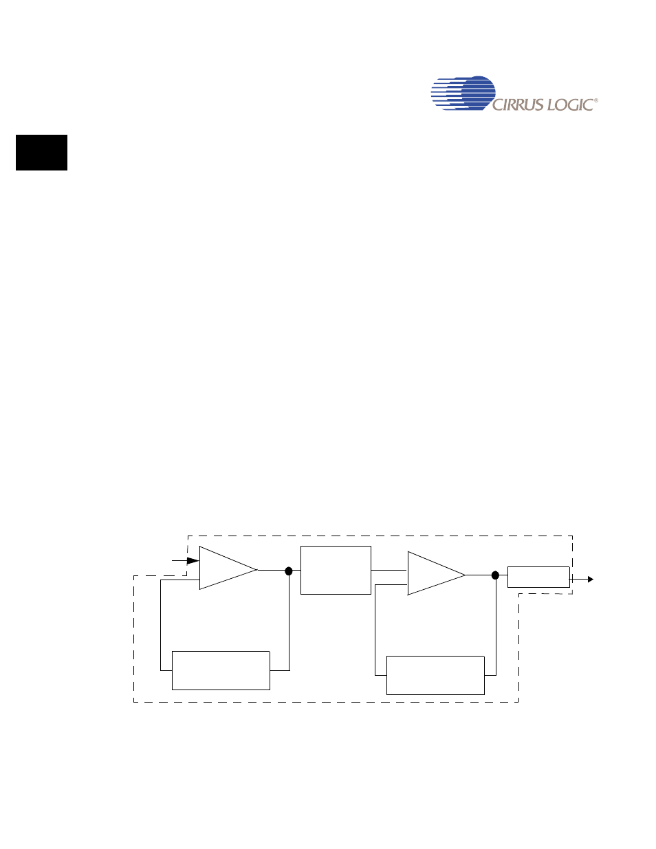
shows the PLL1 structure used in the EP93xx. Since PLL2 is identical to PLL1,
wherever the phrase “PLL1” is used in the figure, it applies to PLL2 as well.
Figure 5-1. Phase Locked Loop (PLL) Structure
14.7456
MHz
Input Divider
2^(PLL1_PS)
PLL1_X1
Feedback Divider
Feedback Divider
PLL1_X2FBD
PLL1_X1FBD
PLL1_X2IPD
PLL1_X2
Fout