2 pixelmode, 11 blink logic, 1 blinkrate – Cirrus Logic EP93xx User Manual
Page 214: 2 defining blink pixels, 2 pixelmode -32, 11 blink logic -32, 1 blinkrate -32 7.4.11.2 defining blink pixels -32
7-32
DS785UM1
Copyright 2007 Cirrus Logic
Raster Engine With Analog/LCD Integrated Timing and Interface
EP93xx User’s Guide
7
7
7
VLineStep = 640 x 4bpp/32
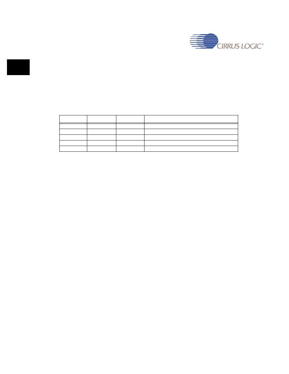
7.4.10.2 PixelMode
Pixel data is transferred from the FIFO to the Video Pixel Mux two 32-bit words at a time (total
of 64 bits). Bits[2:0] of the
register specify the pixel depth as shown in
. The Video Pixel MUX uses the
register to determine how many pixels are
contained in the 64 bits of data. The Video Pixel Mux extracts pixel data from the 64-bits and
passes that pixel data to the BLINK logic one pixel at a time.
Note: All other combinations for these three bits are illegal.
7.4.11 Blink Logic
The blink logic facilitates blinking of individual pixels as they move through the video pipeline.
The blink frequency is controlled by the
register. All blinking pixels blink at the
same rate.
7.4.11.1 BlinkRate
This value is used to control the number of video frames that occur before the pixel value that
is assigned to blink is switched between its non-blinked and blinked values. The actual rate is
calculated by:
Blink cycle = 2 x (1 / VCLK) x HClkTotal x VLinesTotal x (255 - BlinkRate)
where:
VCLK is the basic clock rate of the video logic
HClkTotal is the value contained in the
register
VLinesTotal is the value contained in the
register
BlinkRate is the value contained in the
register
7.4.11.2 Defining Blink Pixels
A blink pixel must be defined before the blink logic is applied to a given pixel. The
registers are used to define the blink pixels.
Table 7-11. Bits P[2:0] in the PixelMode Register
bit P2
bit P1
bit P0
Function
0
0
0
Pixel Multiplexor disabled
0
0
1
4 bits per pixel
0
1
0
8 bits per pixel
1
0
0
16 bits per pixel
1
1
0
24 bits per pixel