2 host controller interface, 1 communication channels, 2 host controller interface -3 – Cirrus Logic EP93xx User Manual
Page 443: 1 communication channels -3, Figure 11-2. communication channels -3
DS785UM1
11-3
Copyright 2007 Cirrus Logic
Universal Serial Bus Host Controller
EP93xx User’s Guide
1
1
1
1
11
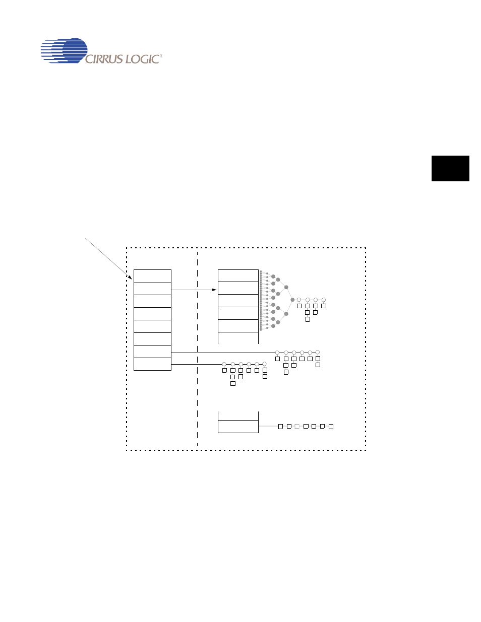
11.2.2 Host Controller Interface
11.2.2.1 Communication Channels
There are two communication channels between the Host Controller and the Host Controller
Driver. The first channel uses a set of operational registers located on the HC. The Host
Controller is the target for all communication on this channel. The operational registers
contain control, status, and list pointer registers. Within the operational register set is a
pointer to a location in shared memory named the Host Controller Communications Area
(HCCA). The HCCA is the second communication channel. The Host Controller is the master
for all communication on this channel. The HCCA contains the head pointers to the interrupt
Endpoint Descriptor lists, the head pointer to the done queue, and status information
associated with start-of-frame processing.
shows the communication channels.
Figure 11-2. Communication Channels
Device Enumeration
OpenHCL
Interrupt 0
Interrupt 1
Interrupt 2
...
Interrupt 31
...
...
Done
Mode
HCCA
Status
Event
Frame Int
Ratio
Control
Bulk
Operational
Registers
Device Register
in memory space
Host Controller
Communications Area
Shared RAM